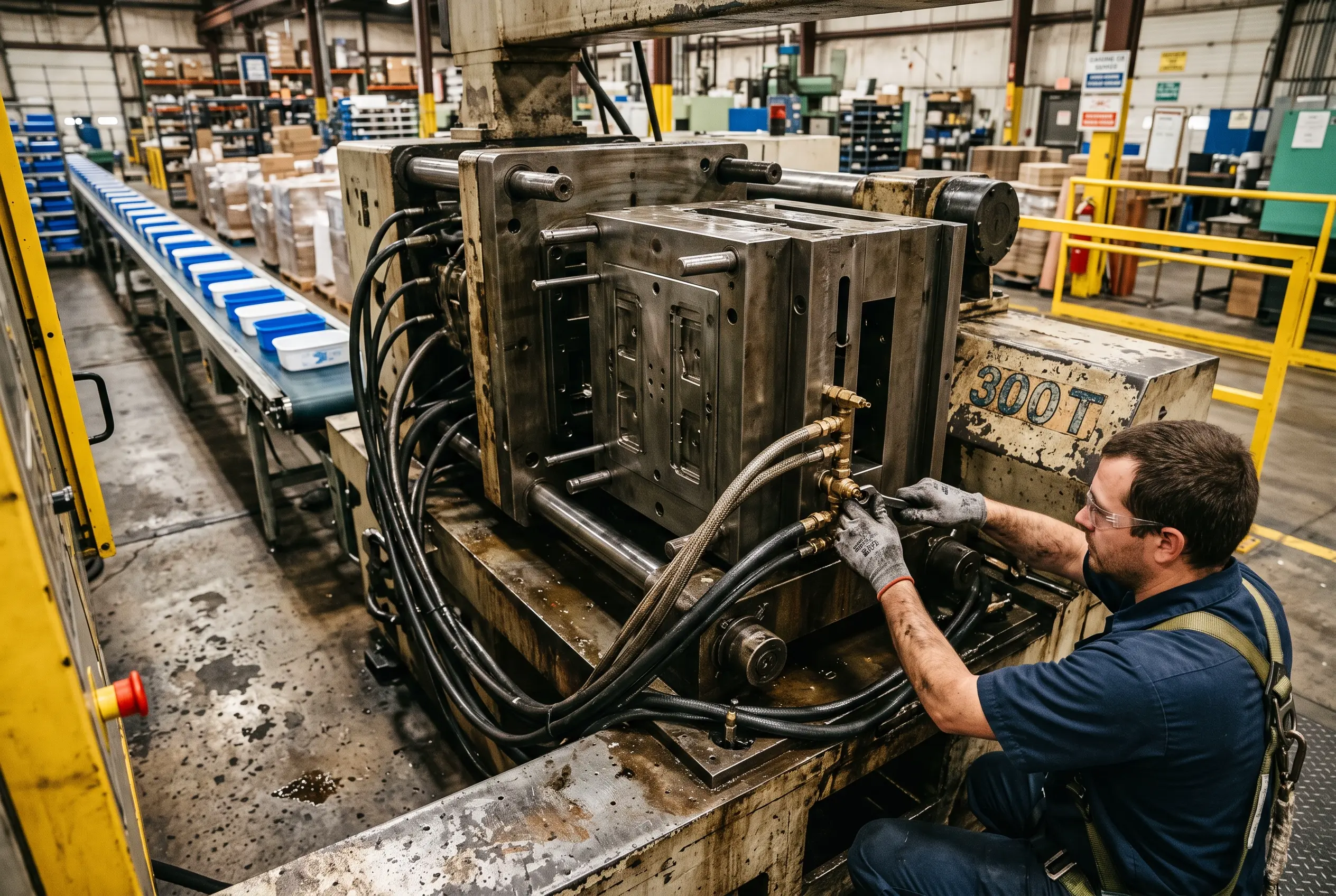
Injection mold design is where product ambition meets manufacturing reality. A well-engineered mold can produce millions of identical parts at tolerances of plus or minus 0.05 mm, while a poorly designed one will saddle your program with sink marks, warpage, flash, and escalating rework costs that compound with every cavity. For hardware startups, the mold represents the single largest capital investment in the production tooling chain — typically $15,000 for a Class 104 prototype mold to $150,000+ for a Class 101 hardened steel production tool capable of exceeding one million cycles. This guide walks through the complete mold design lifecycle across twelve technical sections: from selecting the right mold configuration and applying DFM rules for wall thickness, draft, and rib design, through material selection, SPI mold classification, hot runner systems, conformal cooling channel design, mold flow simulation, scientific decoupled molding with cavity pressure sensors, overmolding and insert molding, micro-molding, maintenance strategy, and total cost of ownership optimization. Whether you are specifying your first aluminum prototype mold or signing off on a 32-cavity Class 101 hot runner tool for a consumer electronics launch, this guide gives you the engineering framework to make decisions that hold up from first shot to million-cycle production.
🏭 $150K+ Tool Investment
A Class 101 hardened steel mold for a consumer electronics enclosure can exceed $150,000 in tooling cost alone. Getting the design right before cutting steel saves $10K-50K in rework.
📐 0.05mm Precision
Precision injection molds hold dimensional tolerances of plus or minus 0.05 mm across a million-cycle run, achieving repeatability that no additive or subtractive process can match at volume.
❄️ 40% Cycle Reduction
Conformal cooling channels — enabled by 3D-printed mold inserts — reduce cycle time by 20-40%, directly improving throughput and lowering per-part cost on high-volume tools.
🔬 80% Less Variation
Scientific decoupled molding with cavity pressure sensors reduces part-to-part variation by over 80%, enabling RJG-style process windows for critical-tolerance applications.
Section 1: Mold Fundamentals — Two-Plate, Three-Plate, and Hot Runner Systems
Every injection mold falls into one of three fundamental architectures, and choosing the right one is the first critical decision in the mold design process. The selection depends on part geometry, production volume, material, gate requirements, and budget constraints.
Two-Plate Molds: The Workhorse
The two-plate mold is the most common configuration, consisting of a cavity half and a core half that meet at the parting line. The runner system runs along this parting line, and the part ejects from the core side. Two-plate molds are simpler, cheaper, and faster to build — typically 20-30% less expensive than a three-plate equivalent. They are ideal for parts where edge gating is acceptable and the parting line location does not create aesthetic concerns. For hardware startups producing under 500,000 units, a two-plate mold in P20 steel is often the optimal choice.
Three-Plate Molds: Pin-Point Gating
When the part requires gating on a surface rather than the edge — common for cosmetic enclosures and parts where gate marks must be hidden — a three-plate mold adds a stripper plate that separates the runner from the part automatically during ejection. This enables pin-point gating at virtually any location on the part surface. The trade-off is higher mold cost, more complex maintenance, and 30-50% more material waste in the runner system. Three-plate molds are preferred for consumer products where surface finish quality is critical.
Hot Runner Systems: Zero Runner Waste
For high-volume production — typically over 100,000 parts — a hot runner system eliminates the cold runner entirely by keeping the material molten through heated manifolds and nozzles directly into the cavity. This means zero runner waste, faster cycle times since there is no runner to cool and eject, and more consistent part quality. Hot runner systems add $8,000-30,000 to the mold cost but pay back rapidly in material savings and throughput. For a part using $3/kg ABS with a 15g runner, a hot runner saves approximately $45 per 1,000 parts in material alone — meaning a $15,000 hot runner system pays back at around 333,000 parts.
💡 When to Choose Each System
- Two-plate mold: Under 500K parts, edge gating acceptable, budget-constrained, simpler geometry
- Three-plate mold: Cosmetic parts requiring hidden gates, multi-gate parts, medium volume (100K-500K)
- Hot runner: Over 100K parts, expensive material, cycle time critical, multi-cavity tools, minimal waste required
Section 2: DFM for Injection Molding — Design Rules That Determine Part Quality
Design for Manufacturing (DFM) is not a suggestion in injection molding — it is the difference between a part that molds cleanly at a 20-second cycle and one that sinks, warps, or sticks in the mold every shot. The following rules are non-negotiable for production tooling.
Wall Thickness Guidelines
Uniform wall thickness is the single most important DFM rule. Variations in wall thickness cause differential cooling rates, leading to sink marks, warpage, and internal stress. Different materials have different optimal wall thickness ranges:
- ABS: 0.8-3.0mm, nominal 1.5-2.5mm
- PC (Polycarbonate): 1.0-4.0mm, nominal 2.0-3.0mm
- PC/ABS blend: 0.8-3.0mm, nominal 1.5-2.5mm
- Nylon 6/6: 0.5-3.0mm, nominal 1.5-2.5mm
- POM (Acetal/Delrin): 0.5-3.0mm, nominal 1.5-2.5mm
- PEEK: 0.5-3.0mm, nominal 1.0-2.0mm
- TPU: 0.5-3.0mm, nominal 1.5-2.0mm
- Glass-filled nylon: 1.0-3.0mm, nominal 2.0mm minimum for fiber distribution
Draft Angles
Without draft angles, the part will not eject cleanly from the mold — leading to drag marks, deformation, and potential mold damage. The minimum draft is 1 degree per side for smooth surfaces, increasing to 2-3 degrees for textured surfaces where the texture acts as micro-undercuts. For deep cores (over 50mm depth), 3-5 degrees is recommended to prevent sticking. Every textured surface requires additional draft proportional to texture depth — a 0.1mm deep texture needs approximately 1.5 degrees of additional draft.
Rib Design
Ribs increase structural stiffness without adding wall thickness, but poorly designed ribs create sink marks on the opposite surface. The golden rule: rib thickness should be 60% of the nominal wall thickness — never more than 70%. For a 2.0mm wall, ribs should be 1.2mm maximum. Rib height should not exceed 3x the nominal wall thickness, and ribs should be spaced at least 2x the wall thickness apart to prevent fill imbalances.
Boss Design and Corner Radii
Bosses for self-tapping screws or threaded inserts must have a wall thickness at the base no greater than 60% of the nominal wall to avoid sink marks. A boss with an outside diameter of 6mm on a 2mm wall should have a root diameter of 3mm and be connected to the wall with a rib rather than placed directly adjacent. All internal corners must have a fillet radius of at least 0.5mm — sharp corners create stress concentrations that reduce impact strength by up to 50% and act as crack initiation points.
Gate Placement and Parting Line Strategy
Gate location determines weld line position, flow length, fiber orientation, and packing pressure distribution. The gate should be placed at the thickest section of the part to ensure proper packing, and as close to the center of the flow path as possible to equalize flow distances. The parting line should follow the largest cross-section of the part to minimize draft requirements and should be located where any flash will be cosmetically acceptable or hidden by assembly.
Section 3: Material Selection for Production Thermoplastics
Material selection drives every downstream decision — shrinkage rates determine cavity dimensions, melt temperature affects mold steel selection, and drying requirements influence production workflow. Here is a comparison of the most common production thermoplastics with their critical molding parameters.
Shrinkage: 0.4-0.7% | Melt: 220-260C | Mold: 40-80C | Drying: 80C for 2-4h. The default choice for consumer electronics enclosures. Excellent surface finish, good impact strength, easy to mold. Cost: $2-4/kg.
Shrinkage: 0.5-0.8% | Melt: 280-320C | Mold: 80-120C | Drying: 120C for 3-4h. High impact resistance, optical clarity, high heat deflection. Used for lenses, medical housings, rugged enclosures. Cost: $4-6/kg.
Shrinkage: 0.5-0.7% | Melt: 240-280C | Mold: 60-90C | Drying: 100C for 3-4h. Combines PC heat resistance with ABS moldability. Preferred for laptop housings, router enclosures, and structural brackets. Cost: $3-5/kg.
Shrinkage: 1.5-2.0% | Melt: 270-300C | Mold: 70-90C | Drying: 80C for 4-6h. High strength, wear resistance, chemical resistance. Requires careful shrinkage compensation. Glass-filled variants reduce shrinkage to 0.3-0.7%. Cost: $4-7/kg.
Shrinkage: 2.0-2.5% | Melt: 190-220C | Mold: 60-90C | Drying: Not typically required. Excellent dimensional stability, low friction, used for gears, clips, and mechanical components. Cost: $3-5/kg.
Shrinkage: 1.2-1.8% | Melt: 370-400C | Mold: 180-200C | Drying: 150C for 3-4h. Aerospace and medical-grade. Continuous use temperature of 250C. Requires specialized high-temp mold tooling. Cost: $80-120/kg.
Shrinkage: 0.5-2.0% | Melt: 180-220C | Mold: 20-40C | Drying: 100C for 2-3h. Overmolding onto rigid substrates. Shore hardness 60A to 80D. Provides grip, impact absorption, and sealing. Cost: $5-8/kg.
Shrinkage: 0.3-0.7% | Melt: 280-310C | Mold: 80-100C | Drying: 80C for 4-6h. 15-30% glass fiber for structural applications. High stiffness, creep resistance. Causes mold wear — requires hardened steel or coated cavities. Cost: $5-9/kg.
Section 4: SPI Mold Classification — Class 101 Through 104
The SPI (Society of the Plastics Industry) mold classification system provides a standardized framework for specifying mold quality, durability, and expected service life. Understanding these classifications is essential for communicating requirements to your toolmaker and budgeting accurately.
🏆 Class 101
1,000,000+ cycles. Hardened steel core and cavity (H13, S7 at 48-52 RC), guided ejection, wear plates, temperature control in core and cavity. Premium mold base. Cost: $80K-250K+. Built for continuous high-volume production.
🥈 Class 102
Up to 1,000,000 cycles. Medium to high volume. Hardened steel cavity and core but with less rigorous temperature control. Cost: $40K-100K. Suitable for established products ramping to volume.
🥉 Class 103
Up to 500,000 cycles. Medium volume. P20 steel (28-32 RC) cavity and core. Good for products with moderate production forecasts. Cost: $20K-50K.
⚙️ Class 104
Under 100,000 cycles. Prototype and pre-production. Aluminum or mild steel cavities. Ideal for design validation and low-volume bridge production. Cost: $5K-20K.
Steel Selection: P20, H13, S7, and Stainless 420SS
Beyond the classification, the choice of mold steel determines wear resistance, thermal conductivity, and corrosion resistance:
- P20 (1.2311): The default general-purpose mold steel at 28-32 RC. Good machinability, adequate for Class 102-103 molds. Pre-hardened — no heat treatment needed after machining. Cost-effective for most consumer product molds.
- H13 (1.2344): Hot-work tool steel hardened to 48-52 RC. Excellent toughness and thermal fatigue resistance. The standard for Class 101 production molds, especially with glass-filled or abrasive materials. Withstands over 1,000,000 cycles with proper maintenance.
- S7 (1.2357): Shock-resistant tool steel at 54-58 RC. Superior impact toughness — ideal for molds with thin core sections or features prone to cracking. Used in high-stress applications and multi-cavity tools.
- Stainless 420SS (1.2083): Hardened to 48-52 RC with excellent corrosion resistance. Required for medical molding (cleanroom), food-contact parts, and when molding corrosive materials like PVC. Prevents rust in high-humidity or condensation environments.
Section 5: Hot Runner Systems — When and Why to Upgrade
Hot runner technology has become standard for high-volume injection molding, and for good reason. By maintaining the runner system at melt temperature, hot runners eliminate cold runner waste entirely — reducing material consumption by 15-40% depending on part geometry, and cutting cycle time by 10-20% since there is no runner to cool and eject.
Hot Runner Gate Types
The gate type at the hot runner nozzle tip determines the vestige appearance, gate freeze time, and flow characteristics:
- Open gate (thermal gate): Simplest and cheapest. Leaves a small vestige. Suitable for non-cosmetic applications and materials that do not string.
- Valve gate: Mechanically closes the gate with a valve pin, leaving a clean mark with no vestige. Essential for cosmetic parts, high-speed cycling, and multi-cavity tools requiring balanced fill. Adds $1,500-4,000 per drop.
- Multi-tip: Splits a single nozzle into 2-8 gate points, reducing hot runner cost per gate. Useful for small parts in multi-cavity layouts.
The decision to upgrade from cold runner to hot runner should be based on a simple payback calculation. If your annual material savings plus throughput gains exceed the hot runner premium within 12-18 months, the investment is justified. For most consumer electronics molds producing over 200,000 parts per year with PC or PC/ABS at $4-6/kg, hot runner is the clear choice.
Section 6: Cooling Channel Design — Conformal vs Straight-Drilled
Cooling time represents 50-80% of the total injection molding cycle. Every second shaved off cooling goes directly to throughput. This makes cooling channel design one of the highest-leverage optimizations in mold engineering.
Straight-Drilled Channels
Traditional cooling uses straight-drilled water lines through the mold base — typically 8-14mm diameter channels spaced 2.5-3.0 diameters from the mold surface and from each other. This approach is cost-effective and easy to machine but cannot follow complex part contours, resulting in uneven cooling and hot spots in areas with deep cores or thick sections.
Conformal Cooling
Conformal cooling channels follow the contour of the part surface, maintaining a consistent distance from the mold wall throughout. This achieves uniform heat extraction, reduces temperature gradients across the part, and delivers measurable improvements:
- Cycle time reduction: Studies consistently report 20-40% cooling time reduction, with some applications achieving up to 63% for parts with deep cores or thick sections
- Warpage reduction: Uniform cooling reduces differential shrinkage, improving flatness and dimensional stability
- Part quality improvement: Eliminates sink marks in thick sections and reduces internal stress
- Throughput gain: A 30-second cycle reduced by 30% yields an additional 1,000 parts per day on a single-cavity tool
Conformal channels are typically manufactured using metal 3D printing (DMLS/SLM) for the mold insert, which is then mounted in a standard mold base. While conformal cooling inserts add $3,000-15,000 per cavity depending on complexity, the cycle time savings pay back rapidly on high-volume tools.
❄️ Baffles and Bubblers for Deep Cores
For deep core pins where straight-drilled channels cannot reach, baffles (deflectors that split cooling flow around a central blade) and bubblers (tubes that direct coolant up through a central hole and back down the outside) provide targeted cooling. Flow rate calculations should ensure turbulent flow — a Reynolds number above 5,000 — for effective heat transfer. Laminar flow reduces cooling efficiency by up to 60%.
Section 7: Mold Flow Analysis — Simulate Before You Cut Steel
Mold flow simulation using tools like Autodesk Moldflow or Moldex3D is the most cost-effective insurance policy in injection mold design. A typical simulation costs $2,000-5,000 and takes 3-5 days, while tooling rework to fix a single defect can cost $10,000-50,000 and add 2-4 weeks to the timeline.
What Simulation Predicts
A comprehensive mold flow analysis provides the following critical predictions before steel is cut:
- Fill pattern: Visualizes how the melt front advances through the cavity, identifying last-fill areas and potential short shots
- Weld line locations: Predicts where flow fronts converge — critical for structural and cosmetic parts. Weld lines can reduce strength by 20-40% at the weld location
- Air traps: Identifies areas where air cannot escape, requiring vent placement or mold modification
- Sink marks: Predicts visible depressions caused by thick sections or insufficient packing pressure
- Warpage analysis: Calculates differential shrinkage and predicts part distortion after ejection — the most valuable output for tight-tolerance parts
- Cooling analysis: Simulates heat transfer through the mold to optimize cooling channel layout and predict cycle time
- Fiber orientation: For glass-filled materials, predicts fiber alignment direction, which affects anisotropic shrinkage and mechanical properties
The typical workflow involves running simulation at the 30% mold design stage, incorporating changes, re-running at 70% completion, and doing a final validation before mold cutting begins. For multi-cavity tools or parts with tight tolerances, simulation is not optional — it is a required engineering step.
Section 8: Scientific Decoupled Molding — RJG Process Windows
Scientific decoupled molding, pioneered by RJG Inc., separates the injection molding process into distinct phases — fill, pack, and hold — each optimized independently using cavity pressure sensor data. This approach reduces part-to-part variation by over 80% and enables a systematic, data-driven process development methodology.
Decoupled Molding III: The Three Phases
The cavity is filled to approximately 95-98% full using velocity-controlled injection. The goal is to fill the cavity as fast as possible without causing defects like flash, burn marks, or gate blush. The fill phase uses a fill time derived from simulation data, not arbitrary machine settings.
Once the cavity is nearly full, the process switches to pressure-controlled packing to complete fill and compensate for volumetric shrinkage. Pack pressure is typically 50-80% of injection pressure and is held until the gate freezes.
After the gate freezes, hold pressure maintains dimensional stability during cooling. Hold pressure is lower than pack pressure and prevents backflow through the gate. The hold phase ends when the part is rigid enough for ejection.
Cavity Pressure Sensors
The backbone of decoupled molding is cavity pressure sensors — typically piezoelectric load cells or strain sensors mounted behind ejector pins or directly in the mold wall. These sensors provide real-time data on what is happening inside the mold, enabling:
- Process repeatability: By monitoring cavity pressure curves shot-to-shot, the process can be held within a tight window
- Variation reduction: RJG data shows decoupled molding reduces part weight variation by 80%+ compared to traditional molding
- Automated quality control: Parts outside the established pressure window are automatically flagged as rejects, eliminating subjective visual inspection
- Troubleshooting: Cavity pressure curves reveal the root cause of defects — short shots, flash, sink, and warpage all leave distinct signatures in the pressure data
For Illuminious injection molding operations, scientific decoupled molding is standard on all Class 101 tools and is available as an upgrade for Class 102-103 molds serving critical-tolerance applications.
Section 9: Overmolding and Insert Molding
Overmolding and insert molding expand the capability of injection molding by combining multiple materials or incorporating metal components into a single molded part.
TPE Overmolding onto Rigid Substrates
Overmolding a thermoplastic elastomer (TPE) onto a rigid substrate — typically ABS, PC, or PC/ABS — creates parts with soft-grip surfaces, sealing properties, and impact absorption. The key challenge is achieving adequate bond strength between the two materials. Bond strength depends on:
- Chemical compatibility: The TPE must be chemically compatible with the substrate material. Consult material suppliers for compatibility matrices
- Substrate temperature: The rigid substrate must be warm enough for the TPE to bond — typically 40-60C above ambient
- Melt temperature: Higher TPE melt temperature improves bond strength but risks degrading the substrate
- Surface preparation: Mechanical interlocking features — grooves, holes, or textures on the substrate — provide physical bond in addition to chemical bond
Metal Insert Molding
Insert molding encapsulates metal components — typically threaded inserts, electrical contacts, or structural reinforcements — within the molded plastic. This is standard practice for electronics enclosures requiring threaded brass inserts for repeated screw assembly. The insert is loaded into the mold either manually (low volume) or via robotic placement (high volume), and the plastic is molded around it. Key considerations include:
- Insert preheating: Metal inserts should be preheated to 80-120C to reduce thermal shock and improve bond strength
- Wall thickness around inserts: Minimum 0.5mm of plastic around the insert to prevent stress cracking
- Knurl design: The insert's outer surface should have knurling or grooves for mechanical interlock
Section 10: Micro-Molding — Parts Under 0.5g
Micro-molding produces parts weighing less than 0.5 grams with features smaller than 100 microns. This specialized discipline requires dedicated tooling, machines, and process expertise — standard injection molding equipment simply cannot achieve the shot-to-shot consistency required.
Specialized Requirements
- Micro-sized screws: Injection screws of 14mm or smaller diameter with precise shot control — a single shot may be less than 0.1g
- Vented barrels: Specialized barrel design to prevent material degradation at micro shot sizes
- Mold features: Features smaller than 100 microns require EDM machining or lithography-based micro-molding techniques
- Handling systems: Parts too small to handle manually require vacuum-assisted or robotic part removal
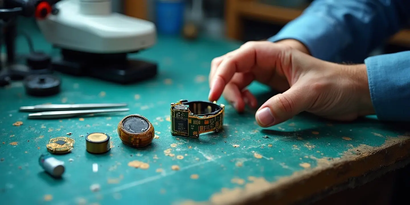
Applications include medical devices (catheter tips, drug delivery components), microelectronics (connector housings, sensor enclosures), and watch components. Illuminious supports micro-molding through partnerships with specialized micro-molding facilities, integrated into our NPI engineering workflow for medical and electronics customers.
Section 11: Mold Maintenance and Lifecycle Management
A Class 101 mold is a precision instrument that requires systematic maintenance to achieve its rated cycle life. Neglecting maintenance leads to dimensional drift, surface degradation, and catastrophic failure — a broken core pin at 400,000 cycles costs $5,000-20,000 in emergency repair and 1-2 weeks of lost production.
Preventive Maintenance Schedule
Inspection: Check cavity and core surfaces for wear, inspect ejector pins for galling, clean vents, lubricate moving components, check cooling channels for scale buildup.
Intermediate service: Replace worn wear plates and leader pin bushings, polish cavity surfaces showing erosion, re-blue parting line, check valve gate operation, descale cooling channels.
Major overhaul: Full mold disassembly, NDT inspection of steel for fatigue cracks, core/cavity refurbishment or replacement of high-wear components, requalification with first article inspection.
Expected Tool Life by Class
- Class 101 (H13/S7 hardened): 1,000,000+ cycles with proper maintenance. Core/cavity refurbishment at 500K extends life to 2M+ cycles
- Class 102 (hardened steel): 500,000-1,000,000 cycles. Refurbishment at 400K extends to 1.5M
- Class 103 (P20): 100,000-500,000 cycles. P20 steel can be surface hardened for extended life
- Class 104 (aluminum/mild steel): Under 100,000 cycles. Aluminum molds (7075-T6) can achieve up to 50,000 cycles with careful process control
Section 12: Cost Optimization — Design Decisions That Drive Tooling Cost
The most expensive features in injection molding are not the parts themselves — they are the mold actions required to produce them. Every undercut, side action, lifter, and thread adds complexity, cost, and maintenance points to the mold. Understanding how design choices drive tooling cost is essential for optimizing the total cost of ownership.
🔧 Side Actions
External undercuts require side core pulls — hydraulic or mechanical slides that add $3,000-8,000 per undercut. Minimize by redesigning with draft or splitting the part.
↗️ Lifters
Internal undercuts need lifter mechanisms — $2,000-6,000 each. Avoid by eliminating internal snaps and using assembled designs where possible.
🌀 Threads
Molded threads require unscrewing cores — $5,000-15,000 per thread. Consider threaded metal inserts instead for screw threads under M6.
🏭 Multi-Cavity
A 4-cavity mold costs roughly 2.0-2.5x a single-cavity mold but produces 4x output. Payback occurs when annual volume exceeds 100,000 parts.
👨👩👦 Family Mold
A family mold produces different parts in one shot — cost-effective for low volume. Risk: if one part changes, the entire mold may need rework.
📊 Total Cost
Tooling cost per part = mold cost divided by expected lifetime parts. A $100K Class 101 mold producing 2M parts costs $0.05 per part in tooling amortization.
Top 10 Mold Design Mistakes and How to Avoid Them
🚫 Critical Mistakes Checklist
- 1. Non-uniform wall thickness — The number one cause of sink marks and warpage. Design for consistent walls and use transitions with a 2:1 taper ratio.
- 2. Insufficient draft — Parts stick, drag, and deform. Minimum 1 degree on all vertical surfaces, more for textured surfaces.
- 3. Sharp internal corners — Stress concentrations reduce impact strength by up to 50%. Add fillet radii of at least 0.5mm at every internal corner.
- 4. Ribs too thick — Ribs over 60% of nominal wall cause sink marks on the show surface. Keep ribs at 50-60% of wall thickness.
- 5. No mold flow analysis — Cutting steel without simulation is gambling $50K+ on an unvalidated design. Always simulate before machining.
- 6. Gate in wrong location — Gating at the thin section instead of the thick section prevents proper packing and leads to short shots and sink.
- 7. Inadequate venting — Trapped air causes burn marks and short shots. Add vents at the last-fill locations identified by simulation.
- 8. Poor cooling channel layout — Uneven cooling causes warpage and long cycle times. Use conformal cooling for complex geometries.
- 9. Wrong steel selection — Using P20 for a glass-filled nylon part leads to rapid cavity erosion. Match steel hardness to material abrasiveness.
- 10. No maintenance plan — Running a Class 101 mold without preventive maintenance guarantees premature failure and costly emergency repairs.
From DFM Review to Million-Cycle Production
Injection mold design is the intersection of material science, mechanical engineering, and manufacturing economics. The decisions made during the DFM review — wall thickness, draft angles, rib proportions, gate placement, steel selection, and cooling strategy — compound across every single shot the mold will ever produce. A well-designed mold with proper simulation, conformal cooling, and scientific decoupled molding produces parts that are indistinguishable from shot 1 to shot 1,000,000. A poorly designed mold will fight you every step of the way, consuming engineering time and eroding margins.
Invest in mold flow analysis before cutting steel. Specify the right mold class for your production volume. Implement cavity pressure sensing on critical parts. And partner with a molder who understands the full lifecycle — from prototype tooling through Class 101 production. At Illuminious, our in-house tool and die shop, 50-1,000T injection molding presses, scientific decoupled molding capabilities, and ISO 9001 quality systems provide hardware startups with a single partner for the complete injection molding journey.