Smart ring manufacturing is arguably the most demanding challenge in wearable electronics: every function of a health tracker must survive inside a ring band smaller than a wedding band. The category is booming — IDC projects 4.9 million smart ring shipments in 2026, up 12.8% year over year, after 49% growth in 2025 and roughly two dozen new models debuting at CES 2026. Yet most entrants underestimate how unforgiving this form factor is: curved rigid-flex PCBs, steel-case coin cells, skin-contact optical sensors and no second chances at rework. This checklist walks through the engineering decisions that separate a smooth EVT-to-PVT ramp from a stalled one.
Tightest Form Factor in Wearables
All electronics must fit inside a band of roughly 2–3 mm internal width — narrower than most 0402 components are long. Smart rings posted 88% shipment growth in 2024, the highest of any wearable category, drawing in startups that often have not priced in this DFM reality.
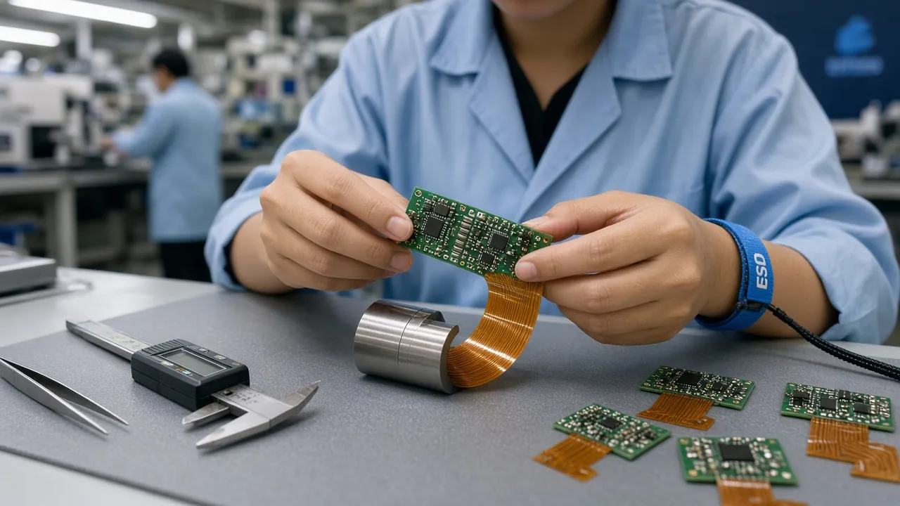
Curved Rigid-Flex PCBA
The main board is a rigid-flex assembly bent into a ring, governed by IPC-2223 bend rules. Static flex bends typically need a radius of about 6x board thickness with rolled-annealed copper; fighting these rules is the number-one cause of field cracks.
Sub-30 mAh Power Budget
Teardowns of category leaders show 26 mAh steel-case coin cells delivering up to 8 days of runtime. Every 0.5 mm of battery diameter is traded directly against ring size and sensor count — capacity, not feature list, defines your SKU matrix.
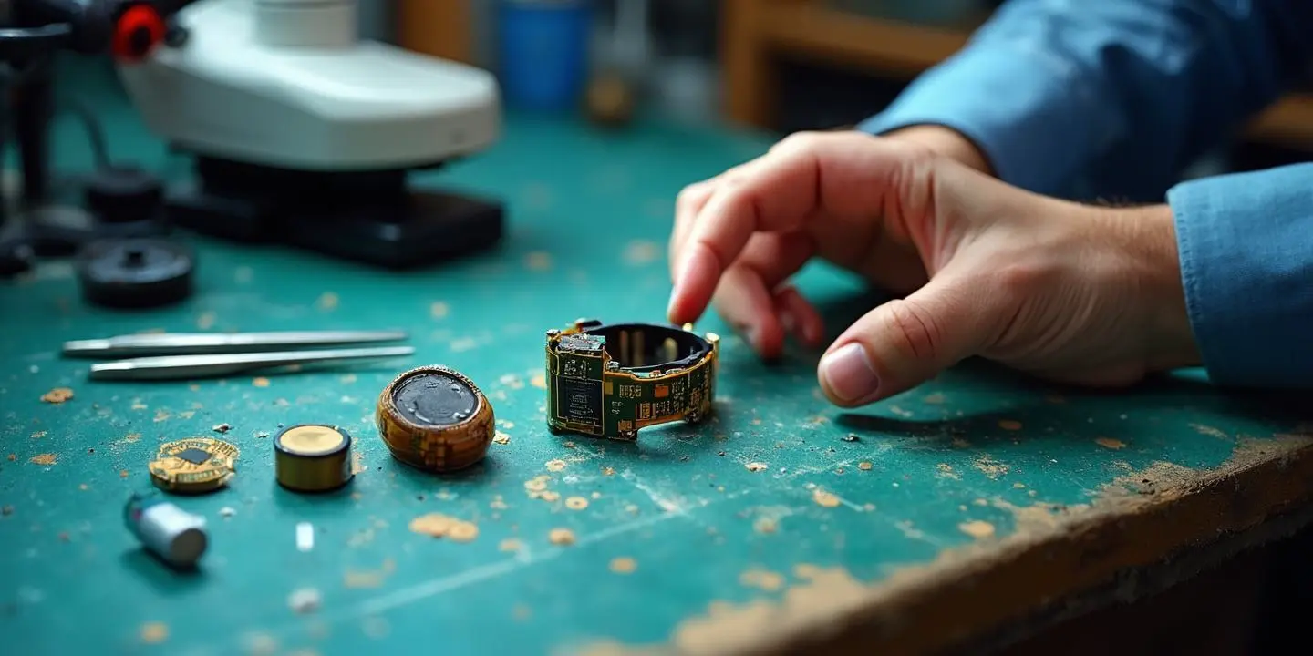
Zero-Rework Assembly
Once the shell is sealed and potted, rework is effectively impossible. Test coverage must move upstream: a ring that fails final QA is close to a total loss at 100% scrap cost, so unit-level testing is engineered in from EVT, not bolted on at PVT.
Why Smart Rings Break Hardware Teams
The smart ring market is expanding fast — IDC expects unit volumes to reach 6.3 million by 2030, and the category dominated CES 2026 headlines with shipments up 49% in 2025. But the market structure is a warning as much as an invitation: one incumbent held roughly 74% of ring shipments in the first half of 2025 according to Omdia data, meaning challengers arrive with thin margins and little room for a failed production ramp. Teams that succeeded with a smartwatch or an earbud frequently misjudge three things about rings: the flex PCB is a structural component, the battery is the mechanical spine, and every test you skip in EVT comes back as scrap in PVT.
The Core Contradiction of the Category
A smart ring packs a full sensor suite — PPG, SpO2, skin temperature, accelerometer — into a sealed, finger-worn enclosure that must survive flexing at ~1 Hz all day. Consumer expectations are set by leaders shipping 8-day battery life, but your PCB real estate is smaller than a fingertip. The checklist below exists to resolve that contradiction early, on paper, where changes cost nothing.
Phase 1: Flex PCB and Rigid-Flex Design Checklist
- Bend radius first: Define the flex bend radius before routing. Per IPC-2223 guidance, static applications generally need at least 6x total flex thickness; a 4-layer flex stack with adhesive can exceed 0.2 mm, which consumes meaningful ring real estate. For a device flexed thousands of times daily, treat the design margin as dynamic-class even if the bend is fixed.
- Rolled-annealed copper: Specify RA copper for all flex layers. Electro-deposited copper cracks at fold lines; RA copper's grain structure survives repeated bending and is standard practice in flex for wearables.
- Coverlay, not solder mask: Flex regions use polyimide coverlay with carefully opened windows. Coverlay openings should leave pad fillets covered; misaligned openings are a recurring flex fab defect that shows up later as intermittent opens.
- Keep components off the bend zone: Leave a component-free flat zone where the battery and antenna sit. Reference open-source smart ring designs: the PCB is deliberately flat and extendable where the battery mounts, cut to length per ring size — that is the pattern to copy.
- Antenna keep-out: BLE and NFC antennas need clearance from the battery steel shell, from the titanium housing and from the user's finger. Reserve antenna area on the rigid section and validate with free-space and on-finger OTA measurements at EVT.
- Teardrops and larger annular rings: Flex design rules require larger annular rings than rigid boards, plus teardrops on every pad-in-plane junction. Your fab partner's flex capability matrix should be a gating input to footprint libraries, not a post-layout audit.
If your team has only designed rigid boards before, treat rigid-flex as a different discipline. Our rigid-flex PCB and PCB assembly services cover the flex fab rules and 01005-class micro SMT that ring PCBA demands.
Phase 2: Sensor Placement Checklist
- PPG optical path: LEDs and photodiode must sit against the finger's skin contact zone with a defined emitter-detector spacing. The optical stack — LED, glass or epoxy window, photodiode, opaque gasket — tolerates almost no stray light; the smallest PPG sensor heads are now around 1 square mm of mount area, but alignment tolerance has not loosened.
- Optical crosstalk control: Isolate the photodiode from LED light paths with opaque barrier gaskets and black potting around the sensor cavity. Light leaking through a translucent housing or an unblocked internal reflection is the classic cause of good bench numbers and garbage on-finger waveforms.
- Skin contact consistency: The sensor window must maintain contact across ring sizes and finger geometries. Design the inner shell profile so the sensor window protrudes slightly and springs against the skin; validate across the smallest and largest ring sizes in your SKU matrix, not just the median.
- Temperature sensor placement: Skin temperature sensing needs thermal isolation from the battery and MCU side of the ring. Put the thermistor near the sensor window, not near heat sources, or your nightly temperature trend will track charger events instead of the wearer.
- Accelerometer orientation: Fix the IMU axis convention in the mechanical model at EVT. Rings rotate on the finger, so motion algorithms must tolerate arbitrary roll — but that is only possible if the reference orientation is consistent across every assembled unit.
Phase 3: Battery and Power Checklist
- Steel-case coin cell: Smart rings use small steel-shell lithium coin cells, typically in the 15–30 mAh class, spot-welded with nickel tabs. Spot-welding parameters — electrode force, weld current, pulse count — must be qualified per cell lot; a cold weld passes assembly and fails in the field.
- Battery as mechanical spine: The coin cell usually doubles as the ring's structural core, with the flex PCB wrapping it. This means battery dimensional tolerance is mechanical tolerance — lock cell dimensions with your cell vendor in writing and re-check incoming lots.
- Protection circuitry: At this size there is no room for a separate protection PCB, so the protection IC lives on the main flex. Verify short-circuit and overcharge behavior at board level, since the cell vendor's certification assumes an external protection scheme.
- Charging coil alignment: Wireless charging via a tiny coil is tolerance-critical. Define the charging puck geometry together with the ring coil at EVT and verify coupling across the full shell tolerance stack; a 0.3 mm stack-up error can drop charge efficiency enough to break your charging UX.
- Capacity vs size trade-off: Every milliamp-hour you add is radius you steal from the sensor cavity. Work the power budget in the other direction: cut current draw first, then size the cell. Category leaders extract 8 days from 26 mAh — proof that firmware efficiency, not cell size, is the lever.
Phase 4: Assembly and Packaging DFM Checklist
- Adhesive bonding vs laser welding: Most rings seal the housing with structural adhesive; some titanium designs use laser welding. Adhesive demands disciplined surface prep and cure scheduling; laser welding demands joint geometry designed for it from day one. Decide at DVT and do not switch mid-ramp.
- Potting vs optical path: Potting protects electronics but any potting compound in or near the PPG cavity changes the optical path. Mask the sensor cavity before dispensing and verify optical output before and after potting on every build.
- Plan for zero rework: After sealing, a failed ring is scrap. Every assembly step needs a preceding test: flex PCBA tested before bonding, sensor calibration before potting, waterproof verification before final QA. The box-build assembly discipline of test-before-seal applies in its strictest form here.
- Waterproofing verification: Ingress protection at IPX8-class depths is usually delivered by gaskets plus adhesive plus potting. Build leak-testing — pressure decay or vacuum bubble — into the line at DVT, not after the first field returns.
- ESD and cosmetic handling: Titanium shells scratch. Specify handling trays, ESD controls and cosmetic inspection criteria in the assembly work instruction; cosmetic scrap at PVT is pure margin loss.
Phase 5: Test Strategy — Test Everything, Before You Seal It
Because rework is near-impossible, smart ring test strategy inverts the usual consumer electronics pattern: every single unit is calibrated and tested, and testing moves upstream of each irreversible step.
- Biosensor calibration per unit: Each PPG/SpO2 pair needs per-unit calibration against a reference — gain, offset and crosstalk compensation coefficients stored in flash. Sampling a few units per lot is not enough when the sensor window alignment varies with every bond.
- On-finger validation fixtures: Bench optical fixtures prove the LEDs fire; they do not prove the waveform is clean through skin. Build a synthetic-skin or finger-phantom fixture at DVT to catch crosstalk and stray-light defects the electrical fixture misses.
- Waterproof test 100%: Pressure-decay leak test every sealed unit. Waterproofing failures are among the top smart ring warranty categories, and 100% inline leak testing is far cheaper than a returns cycle.
- Wireless OTA test: Radiated BLE and NFC performance must be verified per unit with a coupled fixture, since antenna environment changes with every housing lot. OTA throughput and coupling factor belong in the test plan from EVT.
- Battery safety gates: Verify protection trip points and charge behavior on every unit before the housing seals. A cell that charges fine on the bench but trips protection inside a sealed ring is a PVT surprise you cannot open up to fix.
Phase 6: NPI Path — 5, 50, 1,000
The volume ramp pattern that works for smart rings mirrors any tightly-integrated wearable, compressed by the zero-rework constraint:
Prove the bend. Validate flex fab bend radius, copper choice and coverlay alignment with real parts, and take first optical readings through real sensor windows. Expect at least one flex fab respin here — budget for it.
Prove the seal. Qualify bonding or welding, potting, leak testing and per-unit calibration fixtures. Run the full SKU size matrix and confirm charging alignment across tolerance stacks. Design freeze happens at the end of DVT or it does not happen.
Prove the line. Production fixtures, cycle times, yield tracking and 100% test gates under real operator conditions. Yield at PVT, not unit cost, is the number that decides whether mass production is viable.
Start small without penalty. A manufacturing partner with no MOQ lets you run a 5-piece EVT build on the same line and process discipline as your eventual mass production run — so process learning compounds from the first board instead of restarting at each volume tier.
Budget realism matters as much as sequence. Our hardware startup manufacturing costs guide breaks down where ring programs typically overshoot, and our box-build assembly guide covers the test-before-seal sequencing that sealed wearables demand.
01005 and Micro SMT
Ring PCBA lives at the edge of placement capability — 01005 passives and sub-1 sq mm sensor heads, with stencil and reflow profiles tuned for flex.
Flex and Rigid-Flex Assembly
Bend-zone-aware panelization, RA copper specs and coverlay design review before your first flex fab order.
IPC Class 3 Discipline
Class 3 workmanship on every build — the reliability standard a device flexed all day on a finger actually requires.
72-Hour Quick-Turn DFM
Free DFM review and 72-hour quick-turn PCBA iterations keep your EVT respins measured in days, not weeks.
Test-First NPI
Per-unit calibration, leak test and OTA fixtures engineered alongside the assembly process, from EVT fixtures to PVT gates.
US Project Management
US-based program management with direct engineer-to-engineer communication across time zones and ramp phases.
Start Your Checklist Before Your First Flex Quote
The teams shipping smart rings in 2026 are not the ones with the most sensors — they are the ones whose flex PCB bent correctly the first time, whose battery weld process was qualified early, and whose test coverage moved upstream before the first housing was ever bonded. The category's 12.8% annual growth is real, but so is the scrap bin waiting for teams who treat a ring like a small watch.
Ready to Build Your Smart Ring the Right Way?
Send us your flex PCB stack-up and sensor layout for a free DFM review. We will flag bend-zone risks, potting-vs-optics conflicts and test coverage gaps before they cost you a build — from a 5-piece EVT run to mass production, with no MOQ and US-based project management.
Contact Illuminious for a free smart ring DFM review and a 72-hour quick-turn PCBA quote today.