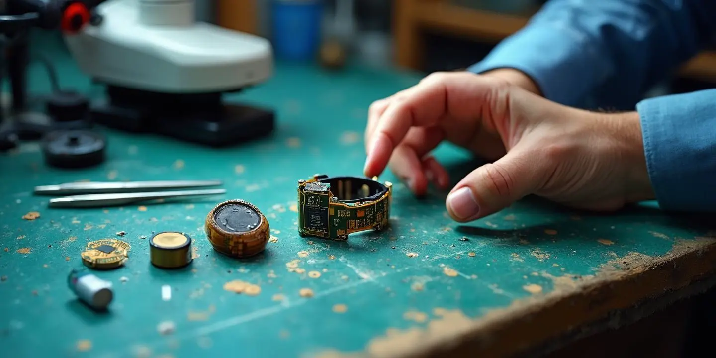
A flex or rigid-flex PCB is not a thin FR-4 board. It is a mechanical part that happens to carry copper. Wearable founders building smart rings, health patches, glasses temples, pet collars and straps often lay out flex the way they lay out rigid boards, then watch traces crack during EVT bend and fatigue testing. This guide covers the design rules that prevent that: bend radius ratios, stackup choices, copper type, stiffeners and transition zones, plus the five mistakes we see most often before a startup's first build.
The short answer
Decide first whether each bend is static, folded once to install, or dynamic, flexed repeatedly in use. Then size the bend radius from total flex thickness, keep vias and components out of the bend, use rolled annealed copper with traces running across the bend, and test five pieces on a flex-cycle fixture before you commit to a housing.
Static vs dynamic: the decision that sets every other rule
IPC-2223, the sectional design standard for flexible and rigid-flex boards, separates two uses. A static or flex-to-install bend is folded during assembly and rarely moves again, such as the flex that wraps a smart ring's battery. A dynamic bend moves throughout the product's life, such as a glasses hinge or a strap that bends every time the user puts it on.
Most wearables contain both. A patch may fold once inside its housing and also flex with the skin. Mark every bend on the fabrication drawing and label its use. If you are unsure, design that bend as dynamic.
Bend radius rules for flexible PCBs
Minimum bend radius is expressed as a ratio of radius to total flex thickness, meaning copper, base polyimide, adhesive and coverlay in the bend area. Fabricator guides based on IPC-2223 commonly use these minimum ratios for bends of 90 degrees or less:
| Flex construction | Static, flex-to-install | Dynamic, repeated flexing |
|---|---|---|
| 1 copper layer | 10 : 1 | 100 : 1 |
| 2 copper layers | 10 : 1 | 150 : 1 |
| 3 or more layers | 20 : 1 | Not recommended |
Worked examples, using typical thicknesses published by one European fabricator: a 90 µm single-layer flex needs about 0.9 mm static or 9 mm dynamic. A 190 µm two-layer flex needs about 1.9 mm static or 29 mm dynamic. A 290 µm four-layer flex needs about 5.8 mm static and should not be used for dynamic bending at all.
Why your numbers may differ
Different IPC-2223 revisions and fabricator checklists quote slightly different static multipliers, and some list 6 : 1 for single-layer static bends. Bends sharper than 90 degrees need a larger radius. Treat the table as a starting point, use the larger value when in doubt, and confirm the final radius with your fabricator against your real stackup.
For a smart ring, the inner diameter is fixed by finger size, so the bend radius is fixed too. The variable you control is thickness. That is why ring and patch designs push toward one or two layers and thin, adhesiveless materials. Our smart ring manufacturing checklist covers the rest of that product's build.
Stackup choices for wearable flex and rigid-flex
Keep layer count low in the bend
Every added layer stiffens the bend and moves copper away from the neutral bend axis, the plane inside the stack that sees no stretch or compression. For dynamic bends, one layer is best and two is the practical limit.
Balance the stack
A symmetrical stack keeps the neutral axis near the copper. For a single dynamic layer, place it in the middle of the stack with matching coverlay on both sides. For two layers, keep them close together on either side of the axis.
Adhesive vs adhesiveless
Adhesive-based laminates cost less and work for many single and double-sided flex parts. Adhesiveless laminates are typically 0.001 to 0.002 inch thinner per substrate, and are generally recommended for rigid-flex because acrylic adhesive expands in the Z axis and can stress plated holes.
Stiffeners where parts sit
Connectors, ZIF tails and component areas on flex need something rigid behind them. Polyimide or FR-4 stiffeners are common. Keep stiffener edges away from the bend so stress does not concentrate at a hard step.
Copper, traces and vias in the bend zone
- Use rolled annealed copper: RA copper has an elongated grain and higher ductility than electrodeposited copper, so it survives repeated bending far better. Run the grain direction along the length of the flex.
- Avoid plating on flexing traces: Plated copper has lower elongation. Fabricators can use pads-only or selective plating so the traces in the bend stay plain RA copper.
- Cross the bend at right angles: Traces should run perpendicular to the bend line. Where they must change direction, use smooth curves, never sharp 45 or 90 degree corners.
- Stagger traces between layers: Traces stacked directly over each other create an I-beam that stiffens the bend and cracks first. Offset them.
- Hatch, do not pour: Replace solid ground and power planes in flex areas with cross-hatched copper, typically at 45 degrees to the bend, and confirm impedance with your fabricator.
- No vias in the bend: Plated holes are rigid and crack under strain. Keep vias, pads and components out of the bend, and keep holes at least 0.050 inch, about 1.27 mm, from the rigid-to-flex transition.
- Teardrops and bigger annular rings: Add teardrops at every trace-to-pad and trace-to-via junction. Flex needs more annular ring than rigid boards; one fabricator asks for a 0.006 inch ring on a 0.008 inch hole.
The 5 mistakes that crack traces in the field
1. Bend radius too tight for the layer count
A team adds layers late to route a denser sensor area, and the flex thickness goes up while the housing radius stays the same. The bend ratio quietly drops below the minimum. Recalculate the ratio every time the stackup changes, not only at the first layout review.
2. Plated through-holes in the flex zone
A via dropped into the bend to save routing space becomes the first crack. Move layer changes into the rigid section or a stiffened area, and respect the transition keepout.
3. Sharp copper corners and the wrong grain direction
Right-angle traces, pads that join traces without teardrops, and RA copper rotated the wrong way all concentrate stress. Each one looks fine in the Gerbers and fails after a few thousand bends.
4. Ignoring the adhesive vs adhesiveless tradeoff
Choosing an adhesive-based stack on cost alone can add enough thickness to break the bend ratio in a ring or patch, and adds Z-axis expansion near plated holes in rigid-flex. Price both options against the bend you need before deciding.
5. Skipping a flex-cycle test at 5-piece EVT
Teams often order housing tooling before any flex has been cycled. Build five pieces, run them on a simple bend fixture at the real radius and angle, and check continuity as you go. A failure at EVT costs a board spin. A failure after tooling costs a tool change and a schedule slip.
Rigid-flex or flex plus connectors?
Rigid-flex joins rigid sections through flex layers built into one board, which removes connectors and cables. It suits wearables where space, weight and vibration resistance matter. It costs more per board and is harder to change late. A separate flex with connectors is cheaper to revise during early EVT. Many startups prototype with flex plus connectors, then move to rigid-flex once the mechanical design is stable. Our rigid-flex PCB page explains what the construction requires.
Free engineering review
We check bend zones, vias, stackup and transitions before you pay.
No-MOQ 5-piece runs
Build just enough flex and rigid-flex boards for EVT bend testing.
72-hour quick-turn PCBA
Fast assembly when iteration speed matters between spins.
US-based PM
One project manager in your time zone from spec to samples.
Test planned early
Continuity and functional checks sized to a 5-piece budget.
One path to volume
The same team takes the design from prototype to production.
A practical flex DFM checklist before you order
- Every bend labeled: static or dynamic, radius, angle and location on the fab drawing.
- Ratio checked: bend radius divided by total flex thickness meets or exceeds the minimum for that layer count.
- Materials called out: RA copper, adhesive or adhesiveless laminate, coverlay type and stiffener material.
- Bend zone clean: no vias, pads or components; traces perpendicular, curved and staggered; hatched planes.
- Transitions safe: holes at least 0.050 inch from the rigid-to-flex line; stiffener edges away from bends.
- Test plan ready: a flex-cycle fixture and pass criteria for the 5-piece EVT build.
For the wider picture, see our complete DFM guide for hardware startups, how we run a 72-hour CAD-to-first-article NPI workflow, and how to budget for small-batch PCBA testing. Our flex PCB, PCB assembly and NPI engineering pages cover each service in detail.
Get your flex design reviewed before you pay
Most flex failures are decided in layout, long before the first bend test. Send your Gerbers, stackup and housing constraints for a free engineering review, then build 5 pieces with no MOQ for EVT. Learn more about our startup program or request a review.