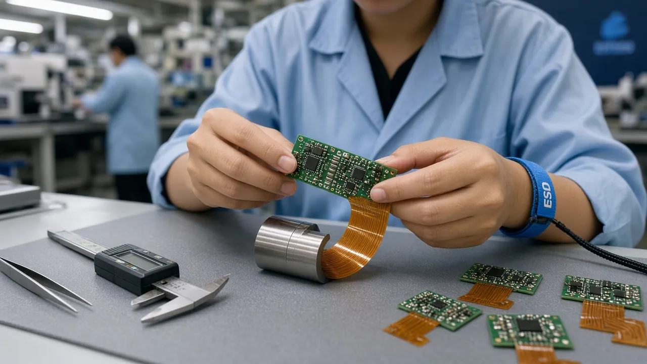
Plastic housings still win most electronics enclosures — but only when the resin, the DFM, and the tooling volume math are decided deliberately. Injection molded plastics remain a $329 billion global market heading toward $456 billion by 2034, and 2026 is rewarding teams that get the plastics decision right early: resin prices are inflating moderately with sharper increases on engineering and flame-retardant grades, OEMs are qualifying molders across multiple regions to de-risk single-source tooling, and insert and overmolding are displacing gaskets and fasteners in smart-device housings. This guide is the counterpart to our aluminum die casting enclosure guide — written for hardware teams that have decided plastic is the right answer, or need the data to defend that call: material selection, UL94 flammability, electronics-driven DFM, EMI strategy, and the tooling break-even math against die casting and CNC.
$329B → $456B Market
Injection molded plastics grow at roughly 3.7% CAGR through 2034. Electronics enclosures remain one of the largest end-use segments.
UL94 V-0 vs V-2
The flammability rating decision drives 15-40% resin cost premium — and it is regulatory-required for many product categories, not optional.
1-2° Draft Standard
Draft, rib and boss rules decide whether your housing ejects cleanly at 30-second cycles or drags, whites out, and sinks around every screw boss.
50-1,000T Presses
Illuminious runs scientific decoupled molding 50-1,000T, insert/overmolding, micro-molding, and Class 101 molds rated 1M+ cycles with in-house tool and die.
When Injection Molding Is the Right Enclosure Process
Choose injection molding for electronics housings when most of these are true:
- Annual volume from ~2,500 units upward. Below that, CNC-machined billet or 3D printing avoids tooling cost entirely; the molding crossover typically lands between 2,500 and 5,000 units for a mid-complexity housing.
- Weight and cost matter more than thermal and EMI brute force. Engineering plastics conduct heat at 0.2-0.5 W/m·K vs ~100 W/m·K for cast aluminum — plastic pairs naturally with shield-can-on-PCBA EMI strategies and active or spread thermal paths.
- Cosmetics are a requirement. Texture, color, soft-touch, and gloss control live in the mold. No machining marks, no anodize batch variation.
- Integration opportunities exist. Snap-fits, molded-in standoffs, bosses for brass inserts, overmolded seals, and living hinges eliminate fasteners and assembly labor at volumes where each saved screw pays for tooling features.
- The product is RF-transparent where it must be. Antenna windows, sensor apertures, and wearable contact zones favor plastic; metal needs break-line engineering.
For the full process-vs-process decision, see the framework at the end and our companion guides: die casting for electronics enclosures, sheet metal fabrication, and CNC machining design.
Material Selection: The Resin Decision Table
The resin choice sets your cost floor, your compliance path, and your field-failure profile. These five families cover 90% of electronics housings:
| Resin | Heat Deflection Temp | Relative Cost | UL94 Rating Available | Best For | Watch Out For |
|---|---|---|---|---|---|
| ABS | ~85-95°C | Lowest | V-0 at flame-retardant grades, HB standard | Consumer electronics housings, set-top boxes, remotes, indoor devices below 80-90°C operating temps | UV and weather resistance without additives; lower impact at low temps |
| PC Polycarbonate | ~130-135°C | High | V-0 and 5VA available | Power devices, outdoor equipment, impact-critical and heat-critical zones, transparent windows | Cost premium, scratch sensitivity, solvent cracking risk |
| PC/ABS Blend | ~110-125°C | Mid | V-0 widely available | The balanced default: better impact than ABS, better flow and cost than PC, automotive and industrial electronics | Maximum temperature still below pure PC |
| PA6-GF30 Glass-Filled Nylon | ~200°C+ as molded | Mid-high | HB typical; FR grades exist | Structural housings, thin-wall strength, high-temp internal brackets and connector bodies, under-hood electronics | Moisture absorption shifts dimensions; anisotropic shrink needs careful gate design; glass marks on A-surfaces |
| LCP / High-Heat | ~250°C+ | Premium | V-0 standard | Near-thermal zones, SMT reflow-compatible connectors and internal structures, micro-molded parts | Cost; only justified where reflow or sustained heat demands it |
Selection heuristics that hold up in practice:
- Consumer indoor device on a budget: FR-ABS. It achieves UL94 V-0 at practical wall thicknesses, flows into thin complex geometry, and keeps unit cost lowest.
- Power, outdoor, or drop-critical: PC or PC/ABS. PC's heat deflection near 132°C and its impact behavior cover power bricks, chargers, industrial HMI, and anything that lives in a hot vehicle cabin.
- Thin-wall structural or load-bearing bosses: PA6-GF30. The 30% glass loading roughly doubles stiffness vs unfilled nylon and lets walls drop below 1.5mm without buckling.
- Near the power section or through reflow: LCP or high-heat grades. If the part sees solder reflow temperatures or sits millimeters from a heatsink, thermoplastics below LCP's class will creep.
UL94 Flammability Ratings Explained for Electronics
UL94 grades describe how a plastic specimen behaves in a controlled vertical or horizontal burn test — and the rating is thickness-dependent, so it applies to your wall stock, not just the datasheet:
| Rating | Test | What It Means | When Required |
|---|---|---|---|
| HB | Horizontal burn | Burns slowly, may drip | Internal brackets, non-accessible parts, lowest-cost consumer goods |
| V-2 | Vertical burn | Self-extinguishes within 30s; flaming drips allowed | Some internal components; not acceptable for most accessible enclosures |
| V-0 | Vertical burn | Self-extinguishes within 10s, no flaming drips | The de-facto requirement for accessible electronics enclosures — power supplies, adapters, anything with mains or lithium batteries nearby |
| 5VA/5VB | Panel burn | No burn-through hole; highest enclosure-level rating | Outdoor electrical enclosures, telecom, unattended equipment |
The cost trade: flame-retardant packages — brominated compounds, phosphorus-based systems — typically add a 15-40% resin premium and can slightly reduce impact strength and flow. Specify V-0 only where the product category, safety standard, or lithium-battery proximity demands it, and specify the wall thickness at which V-0 is certified — a 2.0mm V-0 part may only be V-2 at 1.2mm. Cutting wall below the certified rating silently voids the compliance story. For UV exposure, add stabilizer packages; for EMI, see the next section.
Draft, Rib, and Boss DFM Driven by Electronics Assembly
Generic molding DFM makes a part moldable. Electronics housings must additionally serve the PCBA that lives inside — standoffs, connector windows, display openings, and snap-fit assembly all interact with mold mechanics:
- Draft angles: 1-2° per side on visible surfaces is the reliable standard; 0.25-0.5° minimum is achievable on short, untextured walls. Add 1-1.5° more for textured surfaces — every 0.025mm of texture depth needs roughly 1° of draft to avoid drag whitening on ejection. Deep cores around display windows and battery cavities are where insufficient draft hurts most.
- Wall thickness: keep nominal uniform, typically 1.5-3.0mm for housings. Transitions around display windows should taper, not step — abrupt thick-to-thin changes create sink and hesitation.
- Ribs: 40-60% of nominal wall thickness at the root, height ideally under 3× wall thickness, root fillet at least 0.25× rib thickness. Thicker ribs guarantee visible sink marks on the A-surface above every rib.
- Screw bosses: boss outer diameter roughly 2× the screw hole diameter, boss wall in the same 40-60% band, gussets instead of thick bases. Sink around bosses is the single most common cosmetic defect on consumer housings — the fix is always material removal, never a processing tweak.
- PCB standoffs — brass inserts vs self-tapping: self-tapping screws into plastic strip out on the second service event. Brass heat-stake or ultrasonic inserts give a reusable metal thread, higher torque retention, and no boss cracking — specify them for any fastener a technician will touch more than once, and mold in the correct pilot hole from T1. For one-time assembly at extreme cost pressure, thread-forming screws remain defensible.
- Connector ports and windows: hold port cutout tolerances to ±0.05-0.1mm and design draft so the connector seal face is machined-flat or mold-steel-flat, not on a parting line. Antenna windows: no metal inserts, paint, or plating within the near field.
- Snap-fits: cantilever snaps with strain below the resin limit — under 2% for most PC/ABS — let housings assemble tool-free at line speed. Design the release so the tool needs no side action where possible; every lifter and slider adds cost and maintenance to every shot.
- Gate location: keep knit lines off cosmetic A-surfaces and, critically, away from EMI gasket lands — a knit line on a conductive-coating land creates a coating-thickness discontinuity and a leak point. Flow simulation at DFM catches this before steel is cut.
For mold-side depth — gate systems, cooling, Class 101 tooling steel selection and mold life economics — see our Injection Mold Design Guide 2026.
EMI Strategy for Plastic Housings: Three Paths and When to Switch to Metal
Plastic is transparent to RF, so every plastic-housing electronics product needs an EMI plan. The three workable strategies, compared:
| Strategy | How It Works | Shielding Performance | Cost Profile | Best When |
|---|---|---|---|---|
| Conductive coating on the housing | Copper/nickel/silver paint or vacuum metallization sprayed inside the molded shell | Good — 40-80dB typical when coverage is complete and seams are gasketed | Per-part added process: masking, spraying, thickness QC, spray-line yield loss | Mid volumes; complex geometry; when shielding zones are localized |
| Conductive-filled resin | Stainless fiber, carbon fiber, or nickel-coated graphite compounded into the resin before molding | Moderate — substantially less conductive than coatings; absorption-dominant | High material premium but zero secondary process; excellent repeatability | Very high volumes where per-part coating cost exceeds the resin premium; when repeatability beats peak shielding |
| Shield cans on the PCBA | Stamped metal cans soldered over the RF sections inside a plain plastic housing | Excellent where applied — board-level containment with plastic cosmetics outside | Cannyard adds BOM and rework cost; but housing stays cheapest possible | The modern default for wireless products: contain at the source, keep the housing cheap and beautiful |
Decision logic: if your radiators are a known, bounded set of ICs — an SoC, a radio module, a power section — the shield-can-on-PCBA hybrid almost always wins: cheapest housing, best cosmetics, shielding applied exactly where physics demands it. If emissions are diffuse across the board or regulatory headroom is thin, coatings or filled resins earn their cost. And if thermal, stiffness, sealing, and shielding requirements stack up together, that is the moment to switch to die cast aluminum — a cast housing is its own shield at 60-100+ dB with no secondary process. The crossover is real; our die casting enclosure guide covers exactly when to make it.
Tooling Cost Break-Even: CNC vs 3D Print vs Soft Tooling vs Class 101
The tooling decision is a volume decision. Typical 2026 cost structure for a mid-complexity electronics housing:
| Path | Upfront Tooling | Unit Cost Trend | Sensible Volume |
|---|---|---|---|
| CNC-machined billet | None | Highest, flat with volume | 1-500 units — EVT builds, pilot runs |
| 3D printed SLA/SLS | None | ~$5-50/part | 1-300 units — form-fit visual checks, not material-representative for all resins |
| Soft tooling — aluminum or P20, Class 103 | ~$5,000-25,000 | Low, drops fast with volume | 100,000-500,000 shot life — DVT through early production |
| Class 101 hardened steel | ~$50,000-100,000+ | Lowest | 1,000,000+ shots — full production life |
The break-even logic: the molding unit-cost curve starts steep and flattens hard — for a typical ABS or polypropylene mid-complexity part the crossover where molding beats every alternative lands around 2,500-5,000 annual units. Run the math with all four inputs: tooling amortized over a defensible program life, per-part material at 2026 resin pricing including the FR premium, cycle time × machine rate, and the secondary processes (coating, insert staking, pad printing) that plastic sometimes hides. When insert and overmolding replace gaskets, adhesives, and fastener operations, the per-unit assembly savings frequently justify tooling features that look expensive on a quote — but change the landed-cost math entirely.
The NPI-sequenced path: start billet or printed parts at EVT for mechanical and cosmetic iteration; move to soft tooling at DVT once the design stabilizes — this is when real resin, real cycle, and real draft all get validated; commit Class 101 production steel at PVT with T1 sample approval and Cpk measured on critical dimensions. Our injection molding service runs exactly this ladder, with 72-hour DFM feedback at every phase gate.
Get an Injection Molding DFM Review in 72 Hours
Send your housing CAD, the board it protects, and your annual volume. Upload your design files and our molding team will return a resin recommendation with V-0 wall-thickness certification, draft/rib/boss review, gate and knit-line strategy against your cosmetic and EMI lands, insert and overmolding opportunities, and a tooling path from soft steel to Class 101 mapped to your EVT-DVT-PVT schedule — within 72 hours.
Why Hardware Teams Choose Illuminious for Molded Electronics Housings
- 50-1,000T press range covering micro-molded sensor components to large industrial and medical housings, running scientific decoupled molding for process windows that hold across cavities and shifts.
- Insert and overmolding in-house — brass insert staking, TPE seal overmolds, and multi-shot integration that replaces gaskets and fasteners.
- Class 101 molds rated 1M+ cycles, designed and built by our in-house tool and die team — tooling revisions iterate at the speed of the molding floor, not a subcontractor's queue.
- ISO 8 cleanroom molding for medical devices, alongside ITAR-friendly industrial capacity.
- PCBA + housing integration: the same team builds your board, so standoffs, inserts, connector ports, and shield-can lands arrive matched to the actual assembly — see our box build assembly guide and prototyping-to-production molding guide. For CNC-machined mating parts and post-mold features, our CNC machining service and die casting service complete the mechanical package.