Through-hole assembly for parts that take a load
No CAD yet? Our design team can take it from a sketch or a spec.
Walk Shenzhen factories with us, Dec 6–11. See the tour
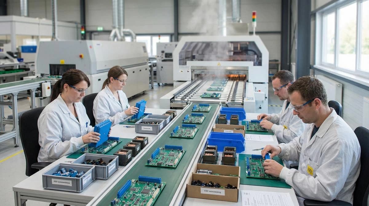
Through-hole assembly solders parts whose leads pass through drilled, plated holes in the board. A joint soldered on the far side of the board is far stronger than one bonded to a surface pad. So connectors, transformers, large capacitors, heavy parts and parts that take force stay through-hole. Illuminious is a U.S. NPI engineering company, and our engineers decide with you which parts go through-hole; the Shenzhen factory then solders them by wave, selective or hand, after the surface-mount steps. Engineered in San Francisco. Prototype builds, DFM and mass production in our own factory in Shenzhen.
Through-hole is one of four declared assembly settings on a standard board order: none, surface-mount, through-hole, or mixed. Mixed is what a product with connectors needs. The rule is simple enough to apply from a schematic, and our engineers apply it during layout, when moving a part from a pad to a hole is still an edit.
How a through-hole board is assembled
Prepare and form
Leads are cut and formed so each part fits its holes.
Insert
Parts are inserted by machine where the design allows, and by hand elsewhere, with orientation checked.
Solder
Wave, selective or hand soldering, by the plan for each joint.
Clean and inspect
Flux residue is removed where the assembly requires it, and joints are inspected by AOI and by eye.
Test
In-circuit and functional tests, as declared on the order.
When should a part be through-hole rather than surface-mount?
When something will pull on it. Board-edge connectors that get plugged and unplugged, screw terminals, panel-mount hardware, and heavy parts on a board that vibrates all belong in holes. The plated barrel and the far-side fillet share the load with the board, instead of relying on a pad's grip on the laminate.
The second case is power. Large inductors, transformers and electrolytic capacitors can come only in leaded packages, and their mass makes a surface-mount version a risk even where one exists. Everything else on a modern board is better as surface-mount: smaller, cheaper and placed by machine.
What is the difference between wave and selective soldering?
Wave soldering passes the whole underside of the board over a standing wave of molten solder, soldering every exposed through-hole joint in one pass. Selective soldering applies solder only to named joints, with a small nozzle following a programmed path. Wave suits boards that are mainly through-hole; selective suits mixed boards with a few leaded parts.
On a wave-soldered board, surface-mount parts on the underside must be masked or glued, and the whole board takes the heat. Selective soldering avoids exposing the surface-mount side to a full wave. Hand soldering remains the answer for low quantities and for joints no machine reaches. Which method each joint gets is part of the assembly plan confirmed in the free engineering review.
How is a mixed-technology board built?
Surface-mount first, through-hole second. Paste is printed, parts are placed and the board is reflowed. Only then are the leaded parts inserted and soldered, because reflow heat would damage many of them and because inserted parts would block the printing and placement steps.
If the board carries surface-mount parts on both faces, the surface-mount sequence runs twice before the through-hole step. Sides populated and technology mix are both declared with the order, so the assembly plan is set before the parts arrive.
How should a board be designed for through-hole soldering?
Size each hole to the lead, not the other way round, with enough clearance for solder to rise through the barrel. Add thermal relief on holes tied to large copper areas. Keep surface-mount parts clear of the selective-solder nozzle's path. Orient parts on wave-soldered boards so the wave reaches every lead.
These are the details that decide whether a through-hole joint fills properly or leaves a void in the barrel. On an engineering project they are settled in layout, as part of our DFM services. On a portal order, the free engineering review flags them before you pay.
Mixed boards also need care in the layout. Keep enough distance between surface-mount parts and through-hole pins on the solder side, so a selective nozzle can reach each pin without touching its neighbors. Put heavy through-hole parts where the board is supported during soldering.
How are through-hole joints inspected?
By looking at both sides of the board and at how far solder has risen through each barrel. A good joint fills the plated hole and shows a fillet on both sides. AOI checks the solder side after wave soldering, and an inspector checks the parts optical inspection cannot see well, such as tall connectors.
IPC-A-610 sets how much barrel fill each class requires. Class 3 asks for more fill than Class 2, which changes the soldering parameters as well as the inspection. That is why the class is stated on the order before the assembly plan is written, and the free engineering review checks hole sizes and thermal relief against it.
Through-hole capability
CapabilityWhat it covers
- Insertion
- Axial, radial and odd-form parts, machine-inserted where the design allows and hand-inserted elsewhere, with leads formed to fit.
- Wave soldering
- Whole-board soldering for designs that are mainly through-hole, with profiled preheat and flux.
- Selective soldering
- Programmed soldering of named joints on mixed boards, keeping heat away from surface-mount parts.
- Hand soldering
- For low quantities, heat-sensitive parts and joints no machine reaches.
- Cleaning
- Flux residue removed after soldering where the assembly requires it.
- Mixed boards
- Surface-mount steps first, then the through-hole step, on one assembly plan.
- Coating
- Conformal coating to protect assemblies from moisture, dust and chemicals.
- Inspection and test
- AOI after wave soldering, ICT and functional test on the factory's 30+ ICT/FCT test stations.
- Workmanship
- Joints judged to IPC-A-610, with Class 3 acceptance when the order states it.
Assembly settings and what each one implies
Two rows carry limits the standard-route configurator enforces: through-hole parts per board and unique part numbers. The other rows list the options you declare and what each one implies; the last row is the published review target. A build outside a limit goes to an engineer for the official quote.
| Declared assembly | What runs | Chosen when |
|---|---|---|
| No assembly | Fabrication only; bare boards ship | You assemble in-house, or the boards are stocked |
| SMT | Print, place, reflow, inspect | The whole design is surface-mount |
| Through-hole | Insert, then wave, selective or hand solder | Connector-heavy, power or older designs |
| Mixed SMT and through-hole | The SMT sequence, then the through-hole step | Surface-mount circuit, through-hole connectors |
| Sides populated | Top side only, or both sides; the SMT sequence runs once per side | Density, or connectors that must face outward |
| Through-hole parts per board | 0 to 5,000, each part counted once however many pins it has | Sets insertion and soldering time |
| Unique part numbers | 0 to 1,000 declared | Sets feeder count and incoming checks |
| Test and programming | Electrical or flying-probe test, AOI, programming, functional test | A functional test needs a defined pass |
| Free engineering review | Within 24 hours on business days after you submit | Review comes before payment |
Recent work: power boards for rack battery units
A startup building battery backup units for AI server racks needed high-current boards with heavy connectors and power parts, stamped copper busbars and a box build, and no vendor owned the whole unit. In the Shenzhen factory, the power boards, the busbars and the final assembly moved into one program, and each unit was tested before it shipped. Read the case study
Order through-hole assembly online
Declare through-hole or mixed assembly on Standard PCB & PCBA, and enter the number of through-hole parts per board. It returns a live supplier price when suppliers can price the build; otherwise a specialist prices it within 24 hours on business days. A mixed board needs an SMT stencil for its surface-mount side. For the whole assembly service, see PCB assembly, and for the surface-mount steps, SMT assembly. For heavy enclosures and harnesses around the board, read the cable harness assembly guide.
Facts and questions
Is through-hole assembly obsolete?
No, it is specialized. Surface-mount carries the circuit on a modern board, and through-hole carries the parts that take mechanical load or come only in leaded packages. "Mixed SMT and through-hole" is a declared assembly setting, not an exception, and connector-heavy products still depend on it.
Can through-hole and surface-mount parts share one board?
Yes, and a product with connectors does. The board runs through the surface-mount sequence first (print, place, reflow) and the through-hole parts are inserted and soldered afterward, because reflow would damage many leaded parts and inserted parts would block printing and placement.
Do you hand-solder anything?
Yes, where no automated method reaches the joint, or where the quantity does not justify a selective-solder program. Which method each joint gets is part of the assembly plan confirmed in the free engineering review. You do not have to specify it per part, but you can mark joints that must be hand-soldered.
Are through-hole parts inserted by machine?
Where the design allows, yes. Axial and radial parts with standard lead spacing go in by machine; odd-form parts, heavy transformers and connectors with unusual pins go in by hand. Declare the through-hole part count on the order, and the review confirms which parts go which way.
Does a through-hole board still need a stencil?
Only for its surface-mount side. A board with no surface-mount parts at all needs no stencil. A mixed board does, and the stencil can be added to the same order as a declared option, so it stays on the same revision history as the board it prints.
How your official quote is prepared
Through-hole and mixed assembly on the standard route show a live supplier price when suppliers can price the build. A specialist prices the rest within 24 hours on business days. An engineer reviews every order before payment, and the official quote is the amount you pay.
- An engineer runs a free engineering review of your files, and nothing is charged when you submit.
- You see the findings first.
- We publish the official quote with an itemized total, lead time and validity window.
- You accept the official quote, and only then does payment open.