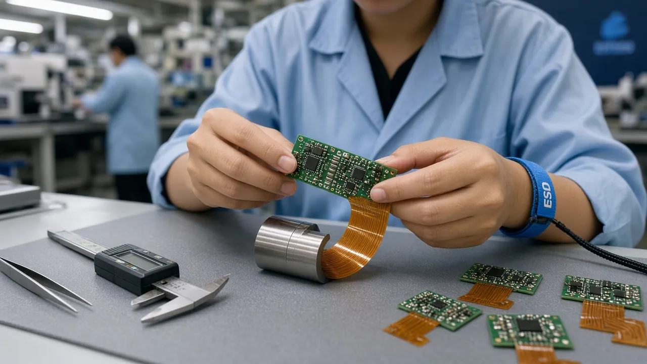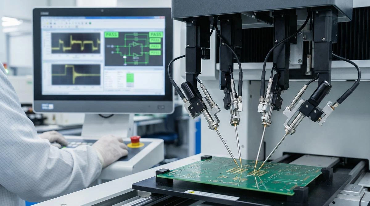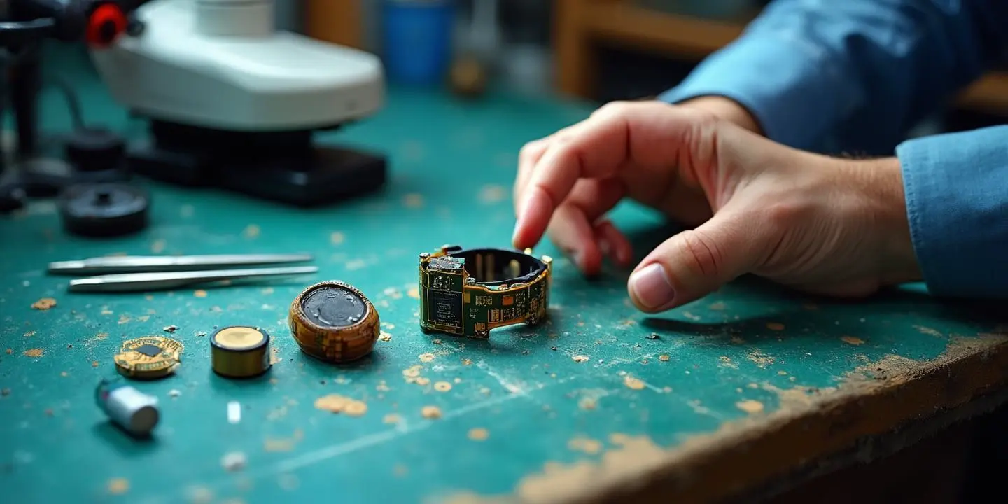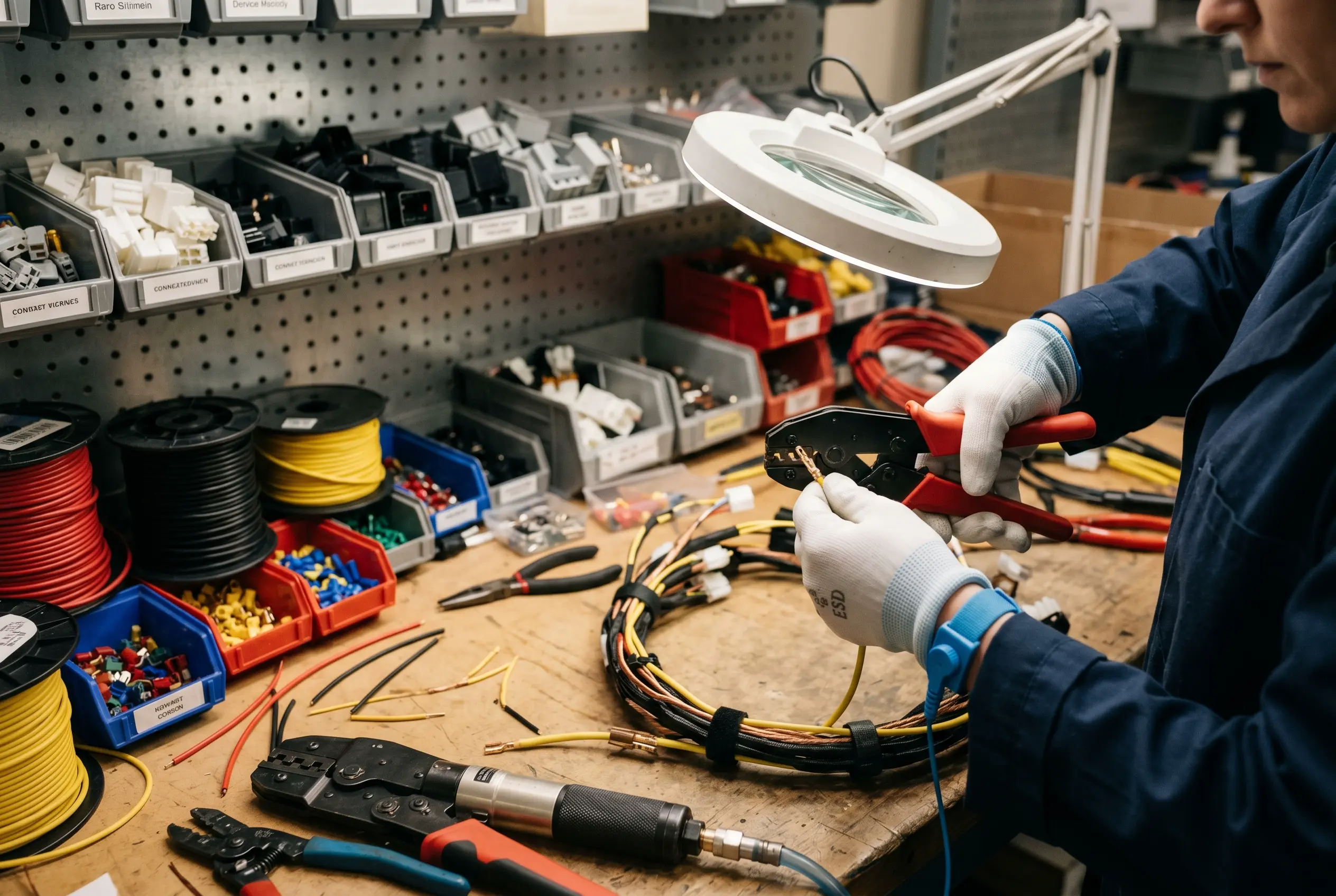
Cable harnesses are the circulatory system of every hardware product — connecting power, signals, and data across PCBs, displays, batteries, sensors, and external interfaces. Yet cable harness design is frequently treated as an afterthought, delegated to the final stages of mechanical integration when PCB layouts are frozen and enclosures are tooled. The result is rushed harness routing, over-specified wire gauges, connector mismatches, and field failures that cost 10-50x more to fix in warranty returns than to design correctly from the start. This guide covers everything hardware engineers and product designers need to know about cable harness assembly: wire gauge and current capacity, connector selection by application, insulation material trade-offs, bend radius and strain relief design rules, overmolding for durability, IPC/WHMA-A-620 testing requirements, and how harness design decisions ripple through box build assembly time and cost.
Wire Gauge and Ampacity
Selecting the correct AWG wire size based on current load, voltage drop, and temperature rise prevents overheating and insulation degradation. Undersized wires cause 30% of harness field failures in consumer electronics products.
Connector Selection
Matching connector type to application — board-to-board, wire-to-board, wire-to-wire, FFC/FPC — determines signal integrity, mating cycle durability, and assembly time. The right connector reduces box build assembly time by 15-25%.
Strain Relief and Overmolding
Proper strain relief design and overmolding extend cable harness life from 500 mating cycles to 10,000+ cycles. Overmolded harnesses achieve IP67 sealing for harsh-environment and medical applications.
IPC/WHMA-A-620 Compliance
The IPC/WHMA-A-620 standard defines acceptance criteria for cable and wire harness assemblies across Class 1, 2, and 3 applications. Certification ensures consistent workmanship quality and electrical reliability.
Wire Gauge Selection: Current Capacity and Voltage Drop
Wire gauge is the most fundamental specification in cable harness design. The American Wire Gauge (AWG) system determines current-carrying capacity (ampacity), voltage drop, weight, and cost. Selecting the correct gauge requires balancing electrical performance, mechanical flexibility, and budget constraints.
AWG Ampacity Reference
Standard ampacity ratings for copper wire with common insulation types (PVC, 80°C rated) provide a baseline for gauge selection. Derate by 15-20% for harness bundles where heat dissipation is restricted.
- 28 AWG: 1.4A max — signal wires, low-power sensor connections, FFC alternatives. Used in dense harness bundles where space is constrained. Voltage drop: ~65mV per foot at 1A.
- 26 AWG: 2.2A max — USB 2.0 data lines, LED power, low-current motor signals. Common in consumer electronics internal harnesses. Voltage drop: ~41mV per foot at 1A.
- 24 AWG: 3.5A max — USB 3.0+ power lines, sensor power, backlight connections. The most common gauge in consumer electronics harnesses. Voltage drop: ~26mV per foot at 1A.
- 22 AWG: 7.0A max — battery leads for small devices, speaker connections, peripheral power. Good balance of flexibility and current capacity. Voltage drop: ~16mV per foot at 1A.
- 20 AWG: 11.0A max — USB-C PD power delivery up to 60W, motor drives, display panel power. Standard for power distribution in compact devices. Voltage drop: ~10mV per foot at 1A.
- 18 AWG: 16.0A max — AC power inlet, high-current motor leads, industrial equipment power. Used in rackmount and industrial harness assemblies. Voltage drop: ~6.5mV per foot at 1A.
Voltage Drop Calculation
For runs longer than 1 meter, calculate total voltage drop to ensure the load receives adequate voltage:
- Formula: V_drop = 2 × L × I × R_per_foot (factor of 2 for round-trip)
- Example: 24 AWG wire, 2m run, 2A load: V_drop = 2 × 6.56ft × 2A × 0.026Ω/ft = 0.68V — significant for 3.3V circuits
- Rule of thumb: Keep voltage drop below 3% of supply voltage for power lines and below 1% for signal references
Connector Selection Guide: Matching Connector to Application
Connector selection impacts signal integrity, mating durability, assembly time, and field reliability. Each connector category serves distinct application requirements:
Molex KK / JST PH / JST XH series: The workhatches of internal cable-to-PCB connections. JST PH (2.0mm pitch) handles signal and low-power applications up to 2A. JST XH (2.5mm pitch) supports up to 3A. Molex KK 254 (0.1-inch pitch) is the industry standard for 5A power and signal with a friction lock that prevents accidental disconnection. Mating cycles: 25-30 minimum, sufficient for assembly and field service.
JST JWPF / Molex Micro-Fit / TE AMPSEAL: Used for harness-to-harness connections inside enclosures or for external device connections. Molex Micro-Fit 3.0 handles 5A per contact in a compact 3.0mm pitch. TE AMPSEAL provides IP67 sealing for automotive and industrial harness applications with up to 14 circuits in a single housing.
0.5mm / 1.0mm pitch FFC connectors: Ideal for display-to-PCB and camera-to-PCB connections in space-constrained devices. Support high-density signal routing with up to 80 contacts in 40mm width. Limited current capacity (~0.5A per contact) restricts use to signal applications. Strain relief is critical — FFC failures account for 22% of display field returns.
USB-C / HDMI / MIPI / LVDS: Impedance-controlled connectors for high-speed data. USB-C handles 20V/5A power delivery alongside 10Gbps data in a reversible form factor. MIPI DSI/CSI connectors route display and camera signals in mobile devices with controlled impedance at 50Ω or 90Ω differential. Always specify impedance-matched cable assemblies — standard wire does not maintain signal integrity above 1GHz.
XT60 / Anderson Powerpole / Barrel Jack: DC power distribution connectors for battery packs, motor drivers, and external power supplies. XT60 handles 60A continuous in a compact form factor with gold-plated brass contacts — the standard for drone and robotics battery harnesses. Anderson Powerpole provides modular stacking for higher current applications.
Insulation Materials: PVC vs Teflon vs Silicone
Wire insulation determines temperature range, chemical resistance, flexibility, and cost. The three most common insulation types in electronics manufacturing each serve different application profiles:
- PVC (Polyvinyl Chloride): The default choice for consumer electronics. Temperature range: -20°C to 80°C. Low cost (~$0.02-0.05 per foot for 24 AWG). Good abrasion resistance and flame retardancy (UL VW-1 rated). Available in every color for harness color-coding. Limitation: Not suitable for high-temperature applications above 80°C and becomes brittle below -20°C.
- PTFE/Teflon: Premium insulation for high-temperature and high-reliability applications. Temperature range: -60°C to 200°C. Excellent chemical resistance and dielectric properties. Low friction coefficient aids routing through conduit. Cost is 5-8x higher than PVC. Required for aerospace, downhole, and automotive engine compartment harnesses.
- Silicone: Extremely flexible across a wide temperature range (-60°C to 200°C). Flame retardant and self-extinguishing. Used in medical device harnesses where steam sterilization is required. Cost is 3-5x higher than PVC. Limitation: Lower mechanical abrasion resistance — typically requires an additional braided shield.
- XLPE (Cross-Linked Polyethylene): Balanced insulation for industrial and automotive harnesses. Temperature range: -40°C to 125°C (150°C for irradiated grades). Excellent moisture resistance and dielectric strength. The standard choice for automotive wire harnesses per SAE J1128 and ISO 6722.
Shielding for EMI Control
In harnesses carrying both high-speed digital signals and sensitive analog lines, EMI shielding is essential to prevent crosstalk and radiated emissions failures during FCC/CE certification:
- Foil shield: 100% coverage, best for high-frequency EMI (>100MHz). Aluminized Mylar with a drain wire for grounding.
- Braid shield: 85-95% coverage, best for low-frequency EMI and mechanical durability. Tin-plated copper braid provides structural reinforcement.
- Combination foil + braid: Maximum protection for mixed-signal harnesses. Required for medical device harnesses near imaging equipment and for automotive camera links.
- Grounding: Connect shield drain wires to chassis ground at one end only to prevent ground loops. For harnesses longer than 300mm, ground at both ends through a low-impedance path.
Bend Radius and Strain Relief Design Rules
Improper bend radius and inadequate strain relief cause the majority of cable harness mechanical failures. These design rules apply to all harness types — from internal flex cables to external user-handled cables:
- Minimum bend radius: For PVC-insulated wires, maintain a minimum bend radius of 10x the cable outer diameter. For Teflon and silicone insulation, 5-8x diameter is acceptable. For multi-conductor harness bundles, use 10x the overall bundle diameter.
- Strain relief at connectors: Every wire-to-connector junction must include mechanical strain relief — either molded strain reliefs (for overmolded cables), cable ties with anchor points (for internal harnesses), or adhesive-lined heat shrink (for field-repairable connections). Without strain relief, pull forces as low as 5N can dislodge crimp terminals from connector housings.
- Service loop: Provide 20-30mm of slack at each connector to allow for thermal expansion, vibration absorption, and one re-termination during field service. Harnesses pulled taut during assembly develop fatigue cracks within 500-2,000 hours of vibration exposure.
- Cable tie placement: Space cable ties every 50-100mm along harness runs. Avoid placing ties directly over bends or connector strain reliefs. Use soft cushion clamps for harness-to-chassis attachment in vibration-intensive applications.
- Routing away from heat: Maintain minimum 10mm clearance from heat sinks, power resistors, and hot components. For harnesses that must pass near heat sources, use high-temperature insulation or add an aluminized fabric heat shield.
Custom Cable Harness vs Off-the-Shelf Cables: Cost Crossover Analysis
One of the most common questions from hardware teams is whether to use off-the-shelf cable assemblies or invest in custom harness design. The answer depends on volume, complexity, and performance requirements:
Off-the-shelf cables win. Standard USB, HDMI, and power cable assemblies cost $1-5 per unit with zero NRE. Custom harness tooling for overmolding starts at $3,000-8,000 per cavity. Use pre-made cables with PCBA standard connectors during prototype and EVT phases.
Transition zone. Semi-custom harnesses using standard connectors with custom wire lengths and crimped terminals become cost-effective. Manual assembly per harness costs $2-8 in labor, offsetting the $3-5 unit cost of off-the-shelf alternatives that may not match exact routing requirements.
Custom harnesses win decisively. Custom harnesses optimize wire lengths, eliminate excess cable bulk, reduce assembly time by 40-60% versus routing individual off-the-shelf cables, and enable overmolding for IP-rated sealing. At 5,000+ units, overmold tooling amortizes to under $0.50 per unit.
Custom always wins when impedance control, mixed-signal isolation, or high-density routing is required. Off-the-shelf cables cannot match the signal integrity performance of a purpose-designed harness with optimized wire routing, twisted pairs, and individual shielding.
Overmolding Cable Harnesses for Durability and Environmental Sealing
Overmolding is the process of injection-molding a thermoplastic or thermoset material directly over a connector and cable junction, creating a sealed, integrated assembly. Illuminious offers insert molding capabilities specifically for cable harness applications:
360-Degree Strain Relief
Overmolding encapsulates the connector-cable junction in a flexible polymer that distributes pull forces uniformly, extending cycle life from 500 to 10,000+ mating cycles.
Environmental Sealing
Molded housings achieve IP67 and IP68 ratings, sealing out dust, moisture, and chemicals. Essential for outdoor, marine, medical, and industrial harness applications.
Brand Integration
Custom colors, logo inserts, and surface textures can be molded directly into the overmold, turning a functional component into a brand element.
Tamper Resistance
Overmolded assemblies cannot be opened without destroying the housing, providing a visual indicator of unauthorized access — critical for medical and security applications.
Consistent Geometry
Injection-molded overmolds guarantee dimensional consistency across thousands of units, ensuring reliable mating with receptacles every time.
Reduced Assembly Time
Overmolded harnesses arrive as single-piece assemblies ready for drop-in installation, reducing box build assembly time by 15-25% compared to multi-component harness routing.
Overmolding Material Selection
The choice of overmold material determines flexibility, chemical resistance, and temperature performance:
- PVC (60-80 Shore A): Cost-effective for consumer electronics. Good flexibility and color options. Temperature range: -10°C to 70°C continuous.
- TPE (Thermoplastic Elastomer): Superior flexibility and tear resistance. Used for premium consumer and medical device cables. Recyclable and compatible with insert molding.
- TPU (Thermoplastic Polyurethane): Abrasion and chemical resistant. The standard for industrial, military, and automotive overmolded harnesses. Temperature range: -40°C to 120°C.
- LSR (Liquid Silicone Rubber): Biocompatible and sterilizable. The choice for medical device cable overmolding. Excellent compression set and temperature stability up to 200°C.
Testing Cable Harnesses: IPC/WHMA-A-620 Standards
The IPC/WHMA-A-620 standard is the only industry-consensus standard for cable and wire harness assembly acceptability. Developed jointly by IPC (Global Electronics Association) and WHMA (Wire Harness Manufacturers Association), it defines visual, mechanical, and electrical acceptance criteria across three product classes:
- Class 1 — General Electronics: Consumer products where cosmetic defects are acceptable if function is maintained. Examples: home appliances, basic consumer gadgets.
- Class 2 — Dedicated Service Electronics: Communications equipment, business equipment, and instruments where extended life and reliable function are expected. Most commercial IoT and smart device harnesses fall into Class 2.
- Class 3 — High Reliability: Products where downtime is unacceptable or life-supporting. Aerospace, medical implants, automotive safety systems, and military electronics. Requires 100% continuity and hipot testing.
Required Tests per IPC/WHMA-A-620
100% electrical continuity verification on every harness. Tests each conductor from connector pin to connector pin. Resistance threshold typically set at <2Ω for short harnesses, scaled by length. Required for all classes.
Applies high voltage between conductors and between conductors and shield/ground. Typical test voltage: 500V DC for 2 seconds (Class 2) or 1500V DC for Class 3 medical/aerospace. Verifies insulation integrity and detects pinhole defects.
Measures resistance between adjacent conductors at 100-500V DC. Minimum acceptable: 100MΩ for assemblies up to 3 meters, 10MΩ for longer assemblies. Critical for high-impedance sensor circuits.
Verifies crimp terminal pull-out force per UL 486A/486B. Minimum pull force for 24 AWG crimp: 15N (1.5 kgf). For 20 AWG: 40N. For 18 AWG: 60N. Samples from each production lot must pass.
100% visual inspection under magnification per IPC/WHMA-A-620 criteria: proper crimp bell mouth, wire brush length, insulation position, conductor damage, and connector seating. Illuminious performs visual inspection at 5-10x magnification for all Class 2 and Class 3 harnesses.
Cable Harness Design Impact on Box Build Assembly
Cable harness design decisions directly impact box build assembly time — often the single largest cost component in final product assembly. Smart harness design can reduce assembly labor by 30-50%:
- Color-coded wires: Assign unique colors to each circuit function (red for power, black for ground, yellow for signal, blue for data). Assembly technicians route connectors by color match, reducing errors and eliminating the need for point-to-point continuity checks during assembly.
- Polarized connectors: Use connectors with physical polarization features — keys, ramps, or asymmetric pin patterns — that prevent incorrect mating. Polarized connectors eliminate the #1 cause of box build defects: mis-mated connectors during final assembly.
- Pre-assembled sub-harnesses: Design the harness as modular sub-assemblies that can be built and tested independently, then snapped together during final box build. This parallelizes assembly workflow and isolates defects to specific sub-harness stations.
- Routing channels and locators: Mold routing features into the enclosure — cable channels, tie-down posts, locator ribs — that guide harness placement without measurement or interpretation. Self-locating harnesses reduce assembly time by 45-60 seconds per unit compared to free-form routing.
- Automated testing integration: Design harness test points into accessible locations — test pads on connector headers, loop-back paths for automated test fixtures — enabling 100% functional testing in under 30 seconds per unit on the production line.
Build Cable Harnesses That Last
Cable harness design is where electrical engineering meets mechanical engineering meets manufacturing process design. The best harnesses are invisible — they route power and signals flawlessly for the entire product life, survive thermal cycling, vibration, and user handling, and assemble in minutes instead of hours. By following the design rules in this guide — proper wire gauge selection, connector matching, bend radius compliance, strain relief, overmolding, and IPC/WHMA-A-620 testing — your hardware product will ship with harnesses that perform reliably from the first unit to the millionth.
Illuminious provides custom cable harness assembly, overmolding, continuity and hipot testing, and IPC/WHMA-A-620 certified workmanship for hardware products at any scale — from prototype runs of 50 units to mass production at 100,000+ units per month. Contact us to discuss your cable harness requirements.