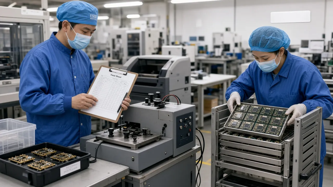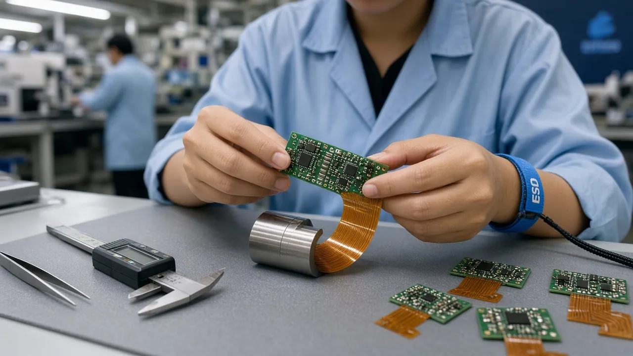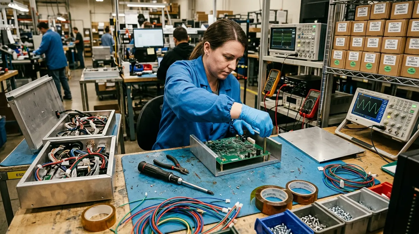
Box build assembly is the final frontier of hardware manufacturing — where a bare PCBA becomes a shippable product. It is the process of integrating printed circuit boards, custom enclosures, cable harnesses, firmware, and functional testing into a complete, market-ready unit. Yet most hardware startups underestimate its complexity, treating it as a bolt-on step after PCBA rather than a discipline that demands its own DFM thinking, quality standards, and supply chain coordination. The result? Products that pass bench testing but fail in the field, assembly costs that balloon to 40-60% of total product cost, and launch delays measured in months, not weeks. This guide walks through every phase of box build assembly — from enclosure material selection through final QA — with the engineering rigor your product deserves. Whether you are building 100 units for a pilot or scaling to 10,000+ per month, understanding the box build process is essential to shipping reliable hardware on time and on budget.
What Is Box Build?
Box build — also called systems integration or electromechanical assembly — transforms a bare PCBA into a finished product by integrating it with a custom enclosure, cable harness, firmware, thermal management, and packaging. It is the most comprehensive level of electronics manufacturing.
Six Assembly Phases
A production-grade box build moves through six distinct phases: enclosure preparation, PCBA integration, cable harness routing, firmware loading, functional testing, and final packaging. Each phase has its own quality gates and failure modes.
40-60% of Product Cost
Assembly labor, testing, enclosures, and packaging typically represent 40-60% of total product BOM cost. Designing for assembly efficiency — fewer screws, snap-fits, self-locating features — can reduce assembly time by up to 35%.
Quality Standards
Box build assemblies are governed by IPC-A-610 for PCBA workmanship, IPC/WHMA-A-620 for cable harnesses, and ISO 9001 for quality management. Medical devices require ISO 13485; automotive requires IATF 16949.
Box Build Defined: Beyond PCBA to Complete Product
A box build encompasses every manufacturing activity required to transform individual components — PCBAs, sheet metal enclosures, injection-molded housings, cable harnesses, connectors, thermal interface materials, firmware, labels, and packaging — into a single functional product ready for end-user shipment. While PCBA assembly focuses on populating a bare board with components, box build is where the board meets its mechanical, electrical, and software environment.
For hardware startups, the transition from PCBA to box build is often where the most expensive surprises occur. A board that passes electrical testing on a bench can fail when mounted inside a sealed enclosure due to thermal constraints. A cable harness that works on the prototype may not fit when the enclosure tolerances shift from 3D-printed to injection-molded parts. Firmware that runs perfectly in development may reveal calibration drift when loaded across a batch of 500 units with component variations.
These are not edge cases — they are the predictable consequences of treating box build as an afterthought. The solution is to design for assembly from day one, integrating mechanical, electrical, and firmware decisions into a unified DFM process.
Phase 1: Mechanical Enclosure Preparation
The enclosure defines the product's physical identity, thermal performance, EMI shielding, and manufacturing complexity. Enclosure material selection is the first major decision in the box build process, and it affects everything from tooling cost to assembly time.
Steel or Aluminum — Best for: rugged industrial, EMI shielding, low-to-medium volume. Sheet metal enclosures are formed using a 250-ton press brake to bend flat stock into 3D shapes. Tooling cost is minimal — often just the bend dies — making sheet metal ideal for volumes of 100 to 10,000 units. Aluminum provides excellent thermal dissipation and EMI shielding. Steel adds structural rigidity for harsh environments. Sheet metal fabrication delivers enclosures in days, not months.
ABS, PC, PC/ABS — Best for: consumer products, high volume, cosmetic finishes. Injection molding tools cost $20,000-$150,000+ depending on complexity, but amortized across 50,000+ units, the per-part cost drops below $2. 50-ton to 1000-ton molding machines accommodate parts from tiny sensor housings to large appliance enclosures. Surface finishes range from matte texture to high-gloss polish. Injection molding services are the volume play for consumer hardware.
ADC12, A380 — Best for: thermal management, structural strength, medium-to-high volume. Die casting produces near-net-shape aluminum parts with excellent dimensional accuracy and thermal conductivity. Tooling costs $15,000-$80,000, viable at 5,000+ units. Ideal for products requiring integrated heat sinks, complex internal geometries, or IP-rated sealing. Die casting services bridge the gap between sheet metal and injection molding.
Enclosure Selection Rule of Thumb
Choose your enclosure material based on volume, environment, and thermal requirements:
- Under 1,000 units: Sheet metal or machined aluminum — no tooling investment required
- 1,000-10,000 units: Sheet metal for industrial, die cast for thermal-intensive designs
- 10,000+ units: Injection molded plastic for consumer products, die cast for structural/thermal needs
- Harsh environment: Die cast aluminum with IP67 sealing and gasketed joints
- EMI-sensitive: Metal enclosure with conductive gaskets at all seams
Enclosure Preparation Steps
- Deburring and cleaning: Remove sharp edges and metal debris from sheet metal and die cast parts. Burrs can cut cable insulation and compromise EMI gasket sealing. Wash aluminum parts to remove cutting fluid residue before anodizing or powder coating.
- Surface finishing: Apply anodizing (aluminum), powder coating (steel), or painting to achieve the required corrosion resistance and cosmetic finish. Anodized aluminum typically adds $2-5 per part; powder coating adds $3-8.
- Threaded insert installation: Press or heat-stake threaded brass inserts into plastic enclosures for repeated screw fastening. Bare plastic threads strip after 5-10 cycles; brass inserts rated for 50+ assembly cycles.
- EMI gasketing: Apply conductive gaskets — finger stock, conductive elastomers, or copper tape — along enclosure seams to achieve shielding effectiveness of 40-80 dB depending on frequency.
- Thermal interface preparation: Apply thermal paste, thermal pads, or phase change materials at PCBA mounting points where heat dissipation is critical. Pre-cut thermal pads ensure consistent application across production units.
Phase 2: PCBA Integration
Mounting the PCBA into its enclosure is where electrical engineering meets mechanical reality. The board must be securely fastened, thermally connected, and electrically isolated from the enclosure where required. Poor mounting design causes mechanical stress on solder joints, thermal hotspots, and short circuits.
- Standoff selection: Hex brass standoffs (M3 or #4-40) provide the standard 6-10mm spacing between PCBA bottom and enclosure wall. Use threaded standoffs for serviceable designs and adhesive standoffs for permanent assemblies. Select standoff height to accommodate the tallest bottom-side components plus 1mm clearance.
- Mounting screw torque: Specifying torque values prevents over-tightening — which cracks the board — and under-tightening — which allows vibration-induced loosening. Typical M3 mounting screws require 0.3-0.5 Nm of torque. Use torque-controlled drivers in production, not hand tools.
- Thermal interface materials: High-power components — CPUs, power regulators, LED arrays — require direct thermal paths to the enclosure or dedicated heat sinks. Thermal paste provides 0.5-3.0 K/W thermal resistance; thermal pads offer 1-6 K/W but are easier to apply consistently in production.
- EMI board-level shielding: Solder-attached EMI shields on the PCBA reduce radiated emissions at the source. When combined with a metal enclosure, the system achieves FCC Class B limits with 6-10 dB of margin.
- Conformal coating consideration: For harsh-environment products, apply conformal coating — acrylic, silicone, or parylene — to the PCBA before installation. This adds 0.5-2.0 to assembly cost but extends product life in humid, dusty, or corrosive environments.
Phase 3: Cable Harness Routing
The cable harness connects the PCBA to power, displays, sensors, user interfaces, and external peripherals inside the enclosure. Proper routing prevents signal interference, mechanical abrasion, and assembly errors. Poor routing adds 10-20 minutes of rework per unit and accounts for a disproportionate share of field failures.
Box build cable harnesses must comply with the IPC/WHMA-A-620 standard, which defines acceptance criteria for wire preparation, crimping, soldering, connector mating, and strain relief across three classes of product reliability. For a deeper dive into harness design rules, see our Cable Harness Assembly Guide.
- Routing channels: Design physical routing channels into the enclosure to guide harnesses along defined paths. This eliminates operator variability and reduces assembly time by 15-25%.
- Strain relief: Every cable-to-connector junction requires strain relief — either molded boots, cable ties anchored to enclosure features, or adhesive-lined heat shrink. Without strain relief, pull forces as low as 5N can dislodge crimp terminals.
- Wire dressing: Bundle parallel wires with cable ties or hook-and-loop wraps every 50-100mm. Separate power and signal harnesses to prevent crosstalk — maintain minimum 10mm separation between high-current and sensitive signal wires.
- Connector keying: Use physically distinct connector types or keyed housings to prevent mis-mating during assembly. Polarized connectors prevent the most common assembly error — reversed connections that destroy components on first power-up.
- Service loops: Provide 20-30mm of slack at each connector for thermal expansion, vibration, and field service. Taut harnesses develop fatigue cracks within 500-2,000 hours of vibration exposure.
Phase 4: Firmware Loading and Configuration
Firmware installation is where software meets the physical product. Each unit receives its operating firmware, calibration data, and unique identifiers during box build — and the process must be repeatable, traceable, and fast enough to keep pace with the assembly line.
- Programming methods: Choose between JTAG/SWD (development and production), ISP/ICSP (in-system programming via header pads), OTA (over-the-air after deployment), or pre-programmed chips (flashed before SMT). Pre-programming eliminates a production bottleneck but requires managing firmware revision control at the component level.
- Calibration: Sensor-based products require per-unit calibration during box build — accelerometer offsets, temperature sensor compensation, ADC gain/offset correction. Store calibration data in on-board EEPROM or OTP memory. Automated test fixtures reduce calibration time from 5 minutes to under 30 seconds per unit.
- MAC address assignment: Networked products require unique MAC addresses. Purchase pre-assigned OUI blocks from IEEE ($1,000 for a 16M block) or use locally administered addresses for non-routed products. Program MAC addresses alongside firmware to streamline production.
- Revision tracking: Every firmware version must be traceable to the hardware revision it runs on. Use a barcode scanner to record PCB serial number, firmware hash, and calibration date in the manufacturing execution system (MES).
Phase 5: Functional Testing
Functional testing — often abbreviated as FCT — is the critical quality gate between assembly and shipment. It verifies that the finished product performs within specification across all operational modes. Skipping or under-scoping FCT is the single most common cause of field returns.
Power-On Test
Verifies current draw, voltage rails, and power sequencing. Catches short circuits and assembly errors before they cause damage. Typical test time: 5-15 seconds per unit.
Communication Test
Validates WiFi, Bluetooth, Ethernet, USB, and serial interfaces. Measures RSSI, throughput, and packet error rate to ensure wireless performance meets spec inside the enclosure.
Sensor Calibration
Tests and calibrates temperature, pressure, accelerometer, and optical sensors against known reference standards. Critical for IoT and medical devices where measurement accuracy is regulated.
Burn-In Test
Runs the product at elevated temperature — typically 40-70°C for 4-24 hours — to surface early-life failures from weak solder joints, marginal components, and thermal stress defects.
FCT Coverage Targets
Industry-standard functional test coverage varies by product category:
- Consumer electronics: 85-95% fault coverage, 30-60 seconds test time per unit
- Industrial equipment: 95-99% fault coverage, 2-5 minutes test time per unit
- Medical devices: 99%+ fault coverage per IEC 62304, full traceability required
- Automotive electronics: 99.5%+ per IATF 16949 PPAP requirements
Phase 6: Final Assembly and Packaging
The last phase transforms a tested functional unit into a shippable product. Labels, serial numbers, accessories, and retail-ready packaging complete the box build process.
- Labeling: Apply regulatory labels — FCC ID, CE mark, UL listing, recycling symbols — plus product labels with model number, serial number barcode, and manufacturing date. Label placement must comply with regulatory requirements for visibility and permanence.
- Serial number assignment: Each unit receives a unique serial number linked to its manufacturing record — PCBA serial, firmware version, calibration data, and test results. This traceability is mandatory for medical and automotive products and best practice for all hardware.
- Accessory insertion: Pack power adapters, user manuals, quick-start guides, and warranty cards into the product box. Design packaging inserts to hold each item securely during shipping — damaged accessories generate 3-5% of warranty claims.
- QA inspection: A final visual and functional check — often sampling 5-10% of production — catches cosmetic defects, missing labels, and packaging errors before products leave the facility.
- Packaging: Retail-ready packaging for consumer products; bulk packaging with ESD protection for B2B products. Drop-test packaging to ISTA standards to ensure survival of standard shipping conditions.
Designing for Assembly: Cost Optimization Strategies
Design for Assembly (DFA) is the engineering discipline of reducing assembly time, complexity, and error opportunities through intentional product design. DFA principles can reduce assembly labor cost by 25-40% without sacrificing product quality.
Reduce screw count. Every screw costs 5-15 seconds of assembly time. Replace screws with snap-fits, captive hardware, or self-locating features wherever possible. A product with 20 screws that could use 8 adds $0.60-1.80 per unit in labor alone.
Use snap-fits for non-serviceable joints. Molded snap-fits eliminate fasteners entirely for internal assembly. Cantilever snaps are simplest; annular snaps suit circular parts. Design snap-fits with deflection within elastic limits — typically under 0.5mm for ABS.
Design parts that only fit one way. Asymmetric mounting features — different diameter standoffs, keyed connectors, alignment pins — make incorrect assembly physically impossible. Poka-yoke design eliminates the most common assembly errors at zero ongoing cost.
Break assembly into parallel sub-assemblies. Instead of a linear 30-minute assembly, design 3 sub-assemblies of 10 minutes each that can be built simultaneously and joined at final assembly. Throughput increases without adding labor.
Use the same screw, standoff, and connector across the product. A single M3 x 8mm screw used throughout simplifies kitting, reduces part numbers, and eliminates the risk of using the wrong fastener. The savings compound across the BOM.
Quality Standards for Box Build Assembly
Box build assemblies are governed by a hierarchy of quality standards that ensure consistent workmanship, reliability, and traceability across the manufacturing process:
- IPC-A-610: The definitive standard for PCBA workmanship — solder joint quality, component placement, conformal coating. Class 1 for consumer, Class 2 for industrial, Class 3 for high-reliability and medical.
- IPC/WHMA-A-620: Acceptance criteria for cable and wire harness assemblies. Covers wire preparation, crimping, soldering, molding, and testing. Required for any box build involving custom cable harnesses.
- ISO 9001:2015: Quality management system standard. Establishes process controls, documentation, corrective action, and continuous improvement. The baseline for any EMS provider.
- ISO 13485:2016: Medical device QMS. Adds design controls, risk management per ISO 14971, sterilization validation, and clinical traceability. Required for medical device box builds.
- IATF 16949:2016: Automotive quality management. Adds PPAP, APQP, FMEA, and SPC requirements. Required for automotive electronics box builds.
When to Outsource Box Build vs In-House Assembly
The decision to outsource box build or keep it in-house is one of the most consequential manufacturing choices a hardware company makes. The wrong choice can cost months of delay and hundreds of thousands in hidden expenses.
Outsource When
- Volume exceeds 500 units/month — in-house assembly cannot scale without dedicated production space, equipment, and trained labor
- Multiple enclosure processes required — sheet metal + injection molding + cable harness + PCBA requires coordination across 4+ specialized vendors
- Regulatory compliance is mandatory — medical, automotive, and aerospace products require documented QMS processes that in-house teams rarely maintain
- Testing requires specialized equipment — burn-in chambers, environmental testers, and automated FCT fixtures cost $50,000-$200,000+ to set up
- Geographic distribution matters — contract manufacturers with facilities near your customers reduce shipping time and cost
The hidden costs of in-house assembly are substantial. Beyond the obvious labor and space requirements, consider: warranty liability for assembly defects, the cost of rework stations and scrap, yield rates that typically run 85-92% for inexperienced teams versus 97-99% for established EMS providers, the overhead of managing component sourcing for enclosures and cable harnesses, and the opportunity cost of engineering time spent on production rather than product development.
A turnkey box build partner — like Illuminious box build services — consolidates PCBA, cable harness manufacturing, enclosure fabrication, firmware loading, FCT, and packaging under one quality system. This reduces coordination overhead, eliminates finger-pointing between vendors, and provides a single point of accountability for the finished product.
Illuminious Box Build Capabilities
Turnkey Box Build
Full integration of PCBA + cable harness + enclosure + firmware + FCT + packaging under one roof. Single-vendor accountability from bare board to shippable product.
Sheet Metal Fabrication
250-ton press brake for steel and aluminum enclosures. No tooling investment. Fast prototyping to production in days. Ideal for industrial and ruggedized products.
Injection Molding
50-ton to 1000-ton molding machines for consumer-grade plastic enclosures. Full tooling design, mold flow analysis, and overmolding capabilities.
Cable Harness Assembly
IPC/WHMA-A-620 certified harness manufacturing. Custom wire preparation, crimping, overmolding, and testing for any harness complexity.
Die Casting
Aluminum die casting for thermally demanding enclosures with integrated heat sinks and complex internal geometries. Medium to high volume cost efficiency.
NPI Engineering Support
NPI engineering services to optimize your design for box build assembly before production starts. DFA reviews, thermal simulation, and test strategy development.
Ship Finished Products, Not Just Boards
Box build assembly is where your hardware becomes a product. Every phase — enclosure preparation, PCBA integration, cable routing, firmware loading, functional testing, and final packaging — must be engineered with the same rigor as your circuit design. Companies that treat box build as a secondary operation consistently underestimate its cost, complexity, and impact on time-to-market.
The most successful hardware companies design for assembly from day one and partner with a turnkey manufacturer that can execute every phase under one quality system. That is how you ship reliable products on schedule, at margin, and at scale.