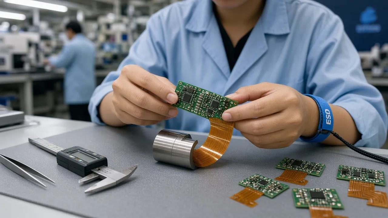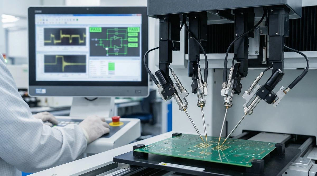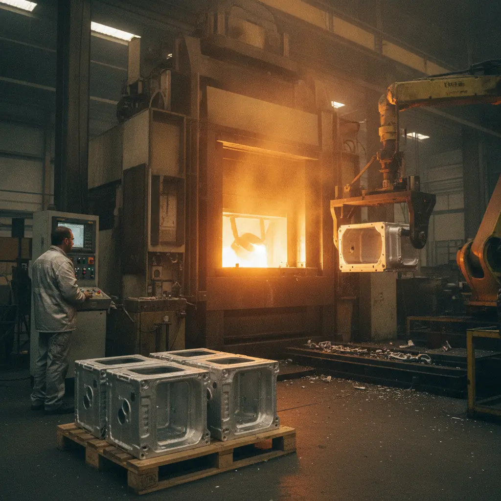
The enclosure is where your PCBA meets the physical world — and for a growing class of electronics, cast aluminum is winning that meeting. Die cast parts for the automotive/EV market are growing at roughly 12.8% CAGR through 2034, and the same forces — lightweighting, thermal density, and EMI-dense AI edge devices — are pushing electronics OEMs to replace plastic housings with die cast aluminum electronics enclosures. A cast aluminum enclosure shields EMI without conductive coatings, conducts heat roughly 10-20x better than plastic for passively cooled edge AI and power electronics, and holds connectors and displays rigid for the life of the product. This guide is written for electronics hardware teams choosing an enclosure process: alloy selection, DFM rules specific to housings, the post-machining and finishing chain, EMI gasket strategy, NPI tooling economics, and a volume-based decision framework against plastic, billet, and sheet metal.
12.8% CAGR
Die cast parts for EV and electrified platforms are growing at roughly 12.8% CAGR 2026-2034 — the same lightweighting and thermal-density forces now reach consumer and industrial electronics.
Built-In EMI Shielding
A cast aluminum wall is a continuous conductive boundary — no conductive coating step, no spray-line yield loss, and shielding effectiveness of 60-100+ dB across 100 MHz-1 GHz when seams and gaskets are designed correctly.
10-20x Plastic Thermal
Cast aluminum conducts heat at roughly 96-110 W/m·K vs ~0.2-0.5 W/m·K for engineering plastics — the difference between a fanless edge AI box and a failed one.
72-Hour DFM
Illuminious runs high-pressure die casting 150-3,000T in A380/A360/ADC12 and zinc Zamak, with in-house CNC post-machining to ±0.01mm and DFM feedback within 72 hours.
Why Cast Aluminum Beats Plastic for Electronics Enclosures — and Where It Doesn't
Plastic enclosures dominated consumer electronics for thirty years because they were cheap, light, and easy. Three trends broke that default:
- EMI-dense edge AI. High-clock SoCs, NPU accelerators, and 5G/Wi-Fi 6E radios inside one small box create a regulatory and functional EMC problem. Plastic needs vapor-deposited or painted conductive coatings to shield — an added process with inconsistent coverage at corners, bosses, and parting lines. Cast aluminum is the shield.
- Thermal density. A 15-40W edge AI module in a sealed, fanless enclosure has nowhere to dump heat except the housing. Aluminum's conductivity advantage means the enclosure itself becomes the heat sink.
- Structural demands. Coax connectors, antenna feed-throughs, DIN-rail mounts, and displays impose loads that glass-filled plastic bosses handle poorly across thermal cycles and drop events. Cast aluminum walls resist creep and keep fastener preload.
The honest counter-case: plastic still wins on tooling cost for mid volumes, on weight, and on design freedom for consumer aesthetics. If your product needs conductive coatings anyway (plastic + paint), tolerates active cooling, and ships under 10K units a year, injection molding with a conductive coating is frequently cheaper. Cross-check our injection molding guide and sheet metal guide for the alternatives — the decision framework at the end of this article puts all four processes side by side. For the macro trend behind the shift, see our coverage of the aluminum die casting market outlook.
Alloy Selection: A380 vs A360 vs ADC12 vs Zinc
Alloy choice is the first fork in the road, and it drives corrosion behavior, castability, cost, and how the enclosure interacts with the PCBA environment. The comparison below covers the alloys that carry most electronics enclosure programs:
| Alloy | Tensile | Yield | Elongation | Corrosion / Character | Best For |
|---|---|---|---|---|---|
| A380 | ~47 ksi | ~23 ksi | ~3.5% | Good; workhorse castability, best balance of properties and cost | Default choice — industrial enclosures, edge AI boxes, power electronics housings |
| A360 | ~46 ksi | ~24 ksi | ~3.5% | Superior corrosion resistance and better ductility; higher Si, lower Cu | Outdoor telecom, marine/coastal, humid or salt-exposed environments |
| ADC12 | ~45 ksi | ~22 ksi | ~3.5% | Cost-optimized Asian standard composition; similar envelope to A380 | High-volume consumer electronics enclosures where unit cost dominates |
| Zamak 3/5 (zinc) | ~41-47 ksi | higher yield | lower | Thin-wall capability, tighter as-cast detail, excellent plating base | Small connectors-adjacent housings, thin walls under 1.5mm, small parts |
Three practical selection notes hardware teams miss:
- Copper content is the corrosion lever. A380 and ADC12 carry 1.5-4% Cu for strength and machinability; A360 caps Cu at ~0.6%. If the enclosure sees condensation, salt fog, or outdoor service — or if you will anodize (high-copper alloys anodize poorly) — A360 is worth the small premium.
- ADC12 vs A380 is largely geographic. They perform nearly identically; ADC12 dominates Asian supply chains and A380 North American ones. If your PCBA and enclosure come from the same Asia contract manufacturer, ADC12 usually prices better for the same performance.
- Zinc beats aluminum for small, thin, detailed parts. Below roughly 300g part weight and 1.5mm walls, Zamak 3/5 fills better at lower injection pressures, holds crisper as-cast detail for cosmetic surfaces, and plates beautifully — but its creep strength limits it in hot environments above ~80°C, which rules it out for most power electronics.
For deeper general alloy and defect coverage, see our Die Casting Design Guide 2026.
DFM Rules Specific to Electronics Housings
Generic die casting DFM gets you a castable part. Electronics enclosures add constraints that exist to serve the PCBA inside, and they should be reasoned about that way — not just as mold-fill rules:
- Uniform wall 2.0-3.5mm — for thermal and EMI reasons, not just fill. A uniform wall doesn't just fill without sinks; it spreads heat evenly so hot spots don't bake one region of your board, and it keeps the EMI boundary continuous. Thin sections under 2.0mm risk misruns that punch invisible holes in your shield; thick sections over 3.5mm sink around bosses and extend cycle time quadratically.
- Draft angles by face class. Exterior cosmetic faces take 1-2°; internal faces that will never see the mold's draw direction constraints take 2-3°; anything texturing or painting adds 1° per 0.025mm of texture depth. Under-drafted walls perpendicular to die pull are the #1 cause of drag marks on sealing surfaces.
- Bosses around PCB standoffs and screw inserts. Design bosses with wall thickness at 40-60% of the nominal wall and core them out; solid bosses sink and porosity concentrates exactly where your insert pulls. Specify self-clinching or press-in inserts (the casting supplier can install them) rather than casting-in threads — as-cast threads below M4 are unreliable and tooling-corrosive.
- Connector port and antenna windows. Cutouts for RJ45, coax, and antenna feed-throughs should be cast in, not machined, wherever tolerance allows — every machined feature is a cost line item. Keep antenna windows at least 10mm from any metallic rib or boss, and remember that die-cast porosity near a cast-in window detunes 5G/mmWave antennas more than most teams expect.
- Seal grooves and gasket design for IP54-IP67. Grooves for O-rings and form-in-place gaskets must be machined, never as-cast — as-cast surfaces are 1.6-3.2µm Ra with porosity that leaks under pressure. Design a flat machined land of at least 2mm around the groove, and put the fasteners inside the seal footprint so the flange compresses uniformly.
- Pressure-equalization vents. A sealed IP67 enclosure that flies, ships, or cycles thermally breathes — pressure differentials pump moisture past gaskets. Cast in a Gore-type vent pocket (cast pocket + installed membrane vent) on the face opposite the main seal.
- As-cast vs machined surfaces — decide deliberately. As-cast is fine for cosmetic and non-mating surfaces at a fraction of the cost; every surface that seals, mates to the PCBA, or carries an EMI gasket should be machined. Marking the split line between the two on the drawing is the single highest-value conversation you'll have with your die casting partner.
Post-Machining and the Finishing Chain
A die cast enclosure is not done when it leaves the die. The chain that follows — machining, finishing, and heat sink integration — is where the enclosure actually becomes a precision electronics component:
- CNC machining of critical interfaces. Mating faces and mounting feet hold ±0.01mm after finish machining; connector bores and coax cutouts hold position tolerances that as-cast features can't. Designate the minimum machining set — every machined face adds fixturing, cycle time, and cost. Typical enclosure programs machine 2-4 faces; the rest stay as-cast.
- EMI-aware finishing choice. Chromate conversion (Alodine/chem-film) preserves electrical conductivity across the surface — the default for EMI gasket lands and grounding points. Powder coat gives cosmetics and corrosion but is an insulator: mask every gasket land, boss thread, and ground point, and expect masking to be a real cost line. Hard anodize can quietly kill EMI performance — the oxide layer is a ceramic insulator, so an anodized flange forces current through gasket penetration points instead of broad contact. If you anodize, mask the gasket lands, or spec chromate there instead.
- Heat sink integration — cast-in vs bonded vs machined. Cast-in fins (in the die, zero assembly cost) are the default for airflow-exposed surfaces and give the best thermal joint. Bonded fins (thermal epoxy or brazing a machined sink to the cast body) win when fins must be tall, thin, and dense — beyond what the die can pull. Machined fins on the casting are the expensive middle ground; use them only when a few critical zones need height and the rest of the geometry is castable.
NPI Tooling Strategy: From EVT Billet to Production Die
The most expensive enclosure mistake in NPI is committing to the wrong tooling at the wrong phase. Three options, three economics:
| Tooling Path | Typical Cost | Life / Volume | Lead Time | Best Phase |
|---|---|---|---|---|
| CNC-machined billet | no tooling; high piece price | unlimited, per part | days | EVT — 10-100 units |
| Gravity casting / soft H-13 tooling | low-moderate tooling | ~1,000 shots | 2-4 weeks | DVT — 100-1,000 units |
| Production H-13 die | $15K-60K+ per die | 100K+ shots | 4-8 weeks | PVT — 10K+ units/year |
Illuminious recommends machined billet enclosures at EVT, soft tooling at DVT, and transitioning to the production die at PVT — the same cadence we apply across NPI programs in our 72-hour rapid prototyping workflow. Billet keeps your firmware-and-thermal team iterating on real metal while the design is still moving; the production die is only worth cutting after the design freezes. The transition point that matters: what changes in the PCBA thermal interface when you go from billet to casting. Die cast aluminum (A380 ~96-110 W/m·K) conducts measurably less than 6061-T6 billet (~167 W/m·K), and die cast parts carry internal porosity that adds thermal resistance. Your thermal budget validated on billet at EVT will run hotter on the casting — derate by 10-20% or re-run the thermal sim against cast material data before PVT, not after.
EMI Gasket Selection for Cast Aluminum Enclosures
The casting gives you the conductive boundary; the gasket closes the seam. Choose the gasket technology early, because each one needs features designed into the casting now — retrofitting gasket features after the die is cut means scrap tooling:
| Gasket Type | Shielding / Seal | Compression | Casting Features Required | Cost Profile |
|---|---|---|---|---|
| Conductive elastomer (die-cut / extruded) | EMI + IP in one gasket | 10-30%, needs groove depth control | Machined O-ring groove, flat 2mm+ land | Moderate part cost; die-cut tooling cheap at volume |
| Finger stock | High EMI, no IP seal alone | spring contact, tolerant of tolerance | Screw bosses or clip slots on the seam | Higher part cost, zero groove machining; best for re-openable seams |
| Form-in-place (FIP) | EMI + IP, complex 3D paths | designed volume, precise | Narrow flat machined channel, 1.0-2.0mm wide | High dispense cost per part; ideal for small, complex, high-value units |
Rules that save tooling: keep the gasket path on one continuous machined face (crossing parting lines or as-cast regions leaks both RF and water); specify chromate conversion under the gasket; and design the fastener pattern so seam deflection under compression stays within the gasket's rated deflection. For high-shielding rack and telecom equipment, finger stock on a chromated flange is nearly unbeatable; for small sealed edge AI units, FIP on a narrow machined channel is the modern default.
Decision Framework: Four Enclosure Processes by Volume and Need
Pull it together. For an electronics enclosure, the process decision is dominated by annual volume, then by EMI and thermal requirements:
| Process | Annual Volume | Tooling | EMI / Thermal | Choose When |
|---|---|---|---|---|
| CNC billet | < 1K units | none; highest piece price | excellent both | EVT, low-volume industrial, design still moving |
| Sheet metal | 1K-10K | low (stamping tools) | good with seamed/RF-welded joints | large racks, chassis, flat geometry — see our sheet metal guide |
| Injection molding | 1K-100K+ | moderate-high (mold) | needs conductive coating + active or added thermal path | consumer aesthetics, weight-critical, non-shielding designs |
| Die casting | 10K+ | high (die), low piece price | best-in-class both, built in | EMI-dense, thermally loaded, structurally demanding enclosures |
That's the series logic: billet for NPI, molding or stamping for the mid-range, and die casting once volume plus shielding plus thermal requirements all point the same direction. Many real products migrate along it — billet at EVT, casting from PVT — and that migration is cheapest when the alloy, DFM, gasket, and machining decisions in this guide were made at design freeze, not after.
How Illuminious Runs Die Cast Enclosure Programs
- High-pressure die casting 150-3,000T in A380, A360, ADC12 aluminum and zinc Zamak 3/5.
- In-house CNC post-machining to ±0.01mm on mating faces, connector bores, and gasket lands.
- Finishing in-house: powder coat, chromate conversion, anodize — with EMI-correct masking on gasket and ground surfaces.
- Insert molding and overmolding for threaded inserts and hybrid metal-plastic enclosures.
- PCBA + enclosure + box build integration — the enclosure team and the SMT line share one DFM loop, so thermal interfaces and EMI gaskets are validated against the actual board, not a drawing assumption.
- DFM feedback within 72 hours of CAD upload — alloy call, draft and wall review, machining set definition, gasket feature plan, and tooling path recommendation by NPI phase.
Get a Cast Enclosure DFM Review in 72 Hours
Send us your enclosure CAD, target volumes, and the board it has to protect. Upload your design files and our die casting team will return an alloy recommendation, draft/wall/machining-set review, EMI gasket feature plan, and a tooling path mapped to your EVT-DVT-PVT schedule — within 72 hours.