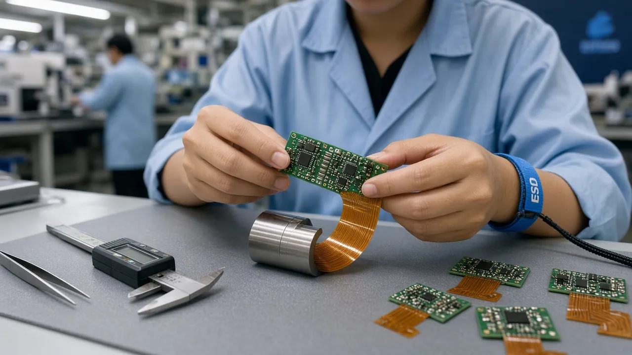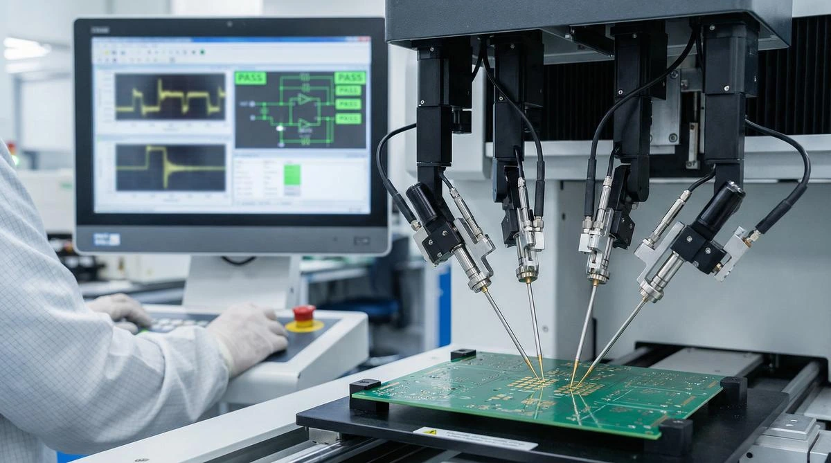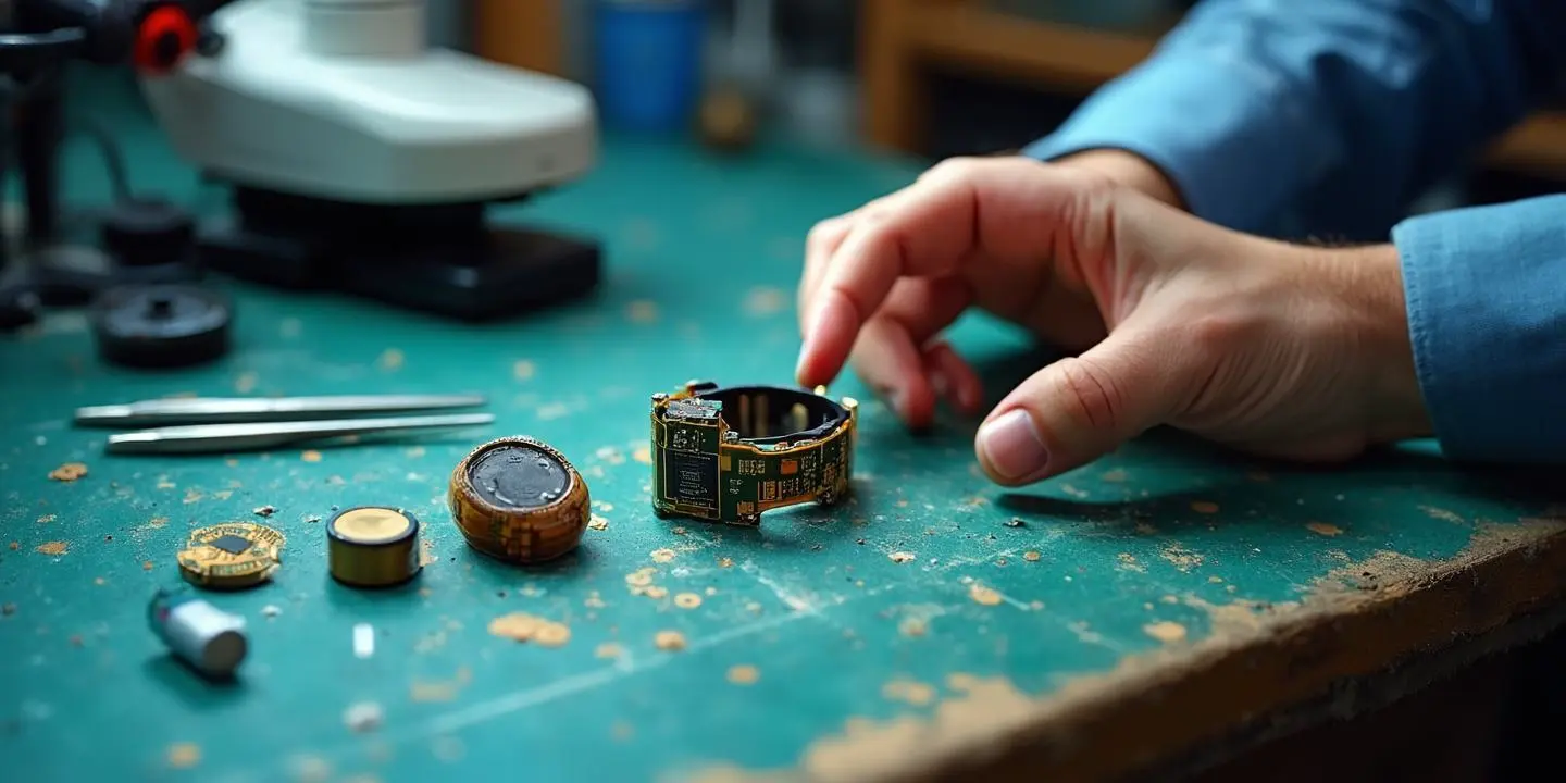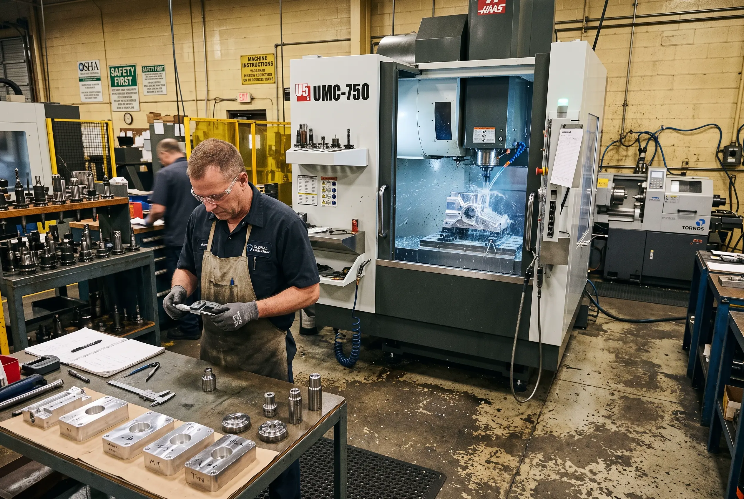
CNC machining remains the backbone of custom precision manufacturing — delivering tolerances down to plus or minus 0.01 mm on materials ranging from aluminum 6061 to titanium Grade 5 and medical-grade PEEK. Whether you are prototyping a robotic actuator bracket, producing aerospace impellers, or machining implantable spinal screws on a Swiss lathe, the design decisions you make in CAD directly determine cycle time, tool wear, part cost, and dimensional accuracy. This guide distills ten sections of practical engineering knowledge covering CNC fundamentals, material machinability ratings, DFM rules for walls and corners, tolerance cost curves, simultaneous 5-axis strategies, surface finish selection, Swiss-type turning for micro parts, cost optimization, CMM inspection workflows, and hybrid manufacturing where additive meets subtractive. For hardware teams transitioning from rapid prototyping to production, these principles separate parts that machine cleanly at scale from those that stall at inspection.
±0.01mm Precision
Precision CNC machining holds tolerances of plus or minus 0.01 mm — roughly one-seventh the diameter of a human hair — on mating surfaces, bearing seats, and sealing interfaces across production runs.
12+ Material Families
From aluminum 6061-T6 at $8/kg to titanium Ti-6Al-4V at $60/kg and medical-grade PEEK at $200/kg, material choice drives 40-60% of total CNC part cost.
5-Axis Single Setup
Simultaneous 5-axis machining eliminates re-fixturing, reducing cumulative datum error by up to 70% on complex geometries like impellers, turbine blades, and joint replacements.
3-5x Cost Multiplier
Tightening tolerance from plus or minus 0.05 mm to plus or minus 0.01 mm increases machining cost by 3 to 5 times due to slower feeds, additional finishing passes, and higher scrap rates.
Section 1: CNC Machining Fundamentals — How Milling and Turning Work
CNC machining is a subtractive manufacturing process where computer-controlled cutting tools remove material from a solid workpiece to create a finished part. Two dominant processes cover the majority of custom precision work: milling and turning.
CNC Milling: 3-Axis, 4-Axis, and 5-Axis
In CNC milling, a rotating cutting tool moves along linear axes relative to a fixed workpiece. The fundamental configurations are:
- 3-Axis (X, Y, Z): The workpiece remains fixed while the spindle moves in three linear directions. Suitable for flat parts, plates, brackets, enclosures, and simple geometries. Most cost-effective for 80% of CNC parts. Maximum part complexity is limited — undercuts and features on multiple faces require re-fixturing between operations.
- 4-Axis (adds rotary A-axis): A rotary table rotates the workpiece around one axis, allowing machining of cylindrical features, cams, and parts requiring multiple faces without manual re-fixturing. Common for aerospace brackets, medical bone plates, and parts with features around a cylinder.
- 5-Axis (adds rotary B-axis): The spindle or workpiece can rotate around two rotary axes simultaneously. This enables machining of complex 3D geometries — impellers, turbine blades, organic shapes — in a single setup. 5-axis reduces handling error, improves surface finish on contoured features, and accesses undercuts impossible on 3-axis machines.
CNC Turning: Lathes and Swiss-Type Machines
Turning rotates the workpiece against a stationary cutting tool, making it ideal for cylindrical parts: shafts, pins, bushings, threads, and rings. Swiss-type lathes guide the bar stock through a sliding headstock, providing support directly at the cutting point — enabling micro-machining of parts under 20 mm diameter with exceptional length-to-diameter ratios.
Subtractive vs Additive: When to Choose CNC
CNC machining excels when you need isotropic material properties, precision tolerances, superior surface finish, or production-grade material certification. Additive manufacturing wins for complex internal geometries, lightweight lattice structures, and ultra-low-volume prototyping. For production parts requiring mechanical strength, CNC remains the default — 3D printing complements rather than replaces it.
Section 2: Material Selection Guide — Machinability, Cost, and Applications
Material selection drives 40-60% of total CNC part cost and directly impacts surface finish, tool life, and achievable tolerance. Below is a practical comparison of the most common machinable materials, ranked by machinability and cost.
The workhorse of CNC machining. Excellent strength-to-weight ratio, superb machinability rating of 190% (relative to free-machining brass), corrosion resistant, weldable, and anodizable. Cost approximately $8-12/kg. Used for brackets, housings, heat sinks, jigs, and prototypes. If you are unsure what to specify, start here.
Aerospace-grade aluminum. Tensile strength of 572 MPa — nearly double 6061. Used for aircraft fittings, gears, shafts, and high-stress components. Machinability rating 160%. Cost $15-25/kg. Not as corrosion resistant as 6061 and more difficult to anodize decoratively.
The premium choice for aerospace and medical. Exceptional strength-to-weight ratio, biocompatible, corrosion resistant. Machinability rating only 22% — meaning tools wear 5-8x faster than aluminum. Requires low cutting speeds, sharp carbide tooling, and generous coolant flow. Cost $55-80/kg. Used for medical implants, aerospace fasteners, turbine components, and high-performance bicycle parts.
Corrosion-resistant stainless for harsh environments. Low carbon content improves weldability. Used in marine, medical, food processing, and pharmaceutical applications. Machinability rating 50%. Cost $12-18/kg. Holds excellent surface finish when polished or electropolished.
High-strength precipitation-hardened stainless. Tensile strength up to 1,034 MPa after H900 heat treatment. Used in aerospace, defense, and oil and gas. Machinability rating 45%. Cost $14-22/kg. Excellent for shafts, gears, and structural components requiring both strength and corrosion resistance.
Free-machining brass. The benchmark for machinability at 100% rating. Excellent for electrical contacts, fittings, valve bodies, and decorative hardware. Cost $8-12/kg. Produces clean chips, holds tight tolerances, and requires minimal finishing.
Electrical and thermal conductivity champion. Used for heat sinks, bus bars, electrical contacts, and heat exchangers. Machinability rating 20% — gummy chips cause built-up edge on tools. Requires sharp tools and careful parameter selection. Cost $10-15/kg.
High-performance engineering polymer. Biocompatible, chemically inert, and capable of replacing metal in many applications. Tensile strength 100 MPa. Used in medical devices, aerospace interiors, semiconductor equipment, and chemical processing. Machinability similar to aluminum but requires careful thermal management to prevent warping. Cost $150-250/kg.
Aerospace-grade amorphous thermoplastic. Flammability rating UL94 V-0, low smoke generation. Used in aircraft interior panels, electrical connectors, and structural components. Cost $80-150/kg. Machines cleanly with carbide tooling.
The go-to plastic for mechanical parts. Excellent dimensional stability, low friction, good wear resistance. Ideal for gears, bushings, rollers, and jigs. Machinability rating very high — cuts like brass. Cost $6-10/kg. Not suitable for high-temperature applications above 100 degrees C.
Material Selection Rule of Thumb
- Prototype and general purpose: Aluminum 6061-T6 — best value, fastest machining
- High stress, aerospace: Aluminum 7075-T6 or Titanium Ti-6Al-4V
- Medical implants and instruments: Titanium Grade 5 or 316L stainless
- Electrical and thermal: Copper C110 or Brass C360
- High-performance polymer: PEEK for medical and chemical, Delrin for mechanical
- Aerospace interior: Ultem PEI for flame retardancy
Section 3: DFM for CNC Machining — Design Rules That Make or Break Your Part
Design for Manufacturing separates parts that machine efficiently from parts that burn tooling budget on avoidable features. These rules come from thousands of production parts and represent the physical constraints of cutting tools.
Wall Thickness
- Metal walls: Minimum 0.8 mm recommended, 1.5 mm preferred for production. Walls thinner than 0.8 mm cause tool deflection, vibration, and poor surface finish.
- Plastic walls: Minimum 1.5 mm recommended, 2.5 mm preferred. Plastics flex during machining, requiring thicker walls and rigid fixturing.
Corner Radii — The Non-Negotiable Rule
Because CNC cutting tools are cylindrical, sharp internal corners are physically impossible. Every internal corner must have a radius at least equal to the tool radius. The practical rules are:
- Minimum internal radius: R 0.5 mm for shallow pockets (under 3 mm depth)
- Standard internal radius: R 1.0 mm to R 3.0 mm for most pockets
- Corner radius formula: R = (pocket depth / 10) + 0.5 mm. For a 30 mm deep pocket, minimum R = 3.5 mm
- Tool diameter relationship: Tool diameter = pocket depth / 5. A 30 mm deep pocket needs a minimum 6 mm diameter tool
Hole Design
- Standard depth: 3x diameter for standard drilling
- Deep holes: Up to 5x diameter with peck drilling cycle
- Maximum practical depth: 10x diameter with specialized tooling
- Thread minimum: M2 (or #0-80 UNF) for general use, M3 preferred for production
- Thread depth: 1.5x diameter for aluminum, 2x diameter for steel
Pocket and Channel Design
- Pocket corner radii: Must equal the tool radius. Design corners at R 1.5 mm or larger to allow standard tooling
- Avoid deep narrow channels: Width-to-depth ratio should exceed 1:3. Channels narrower than 2 mm wide and deeper than 6 mm cause tool breakage
- Floor radii: Internal pocket floors need R 0.5 mm minimum fillet to avoid stress concentration
Undercuts and Side Features
Undercuts require special tooling or multi-axis setups. If unavoidable, keep undercut depth under 2 mm and width wider than 4 mm to allow standard T-slot or dovetail cutters. Always flag undercuts in your CAD model for DFM review.
Top 5 DFM Mistakes That Kill CNC Parts
- Sharp internal corners: The #1 cause of DFM rejection. Always radius your corners.
- Walls too thin: Under 0.8 mm in metal causes chatter and poor tolerance.
- Deep pockets with small radii: Requires specialized long-reach tools that deflect and break.
- Unnecessarily tight tolerances: Specifying plus or minus 0.01 mm on non-critical features multiplies cost by 3-5x.
- Complex undercuts: Often require custom tooling or 5-axis repositioning, adding significant cost.
Section 4: Tolerance Optimization — When Precision Matters and When It Does Not
Specifying the right tolerance is the single highest-leverage decision in CNC cost optimization. Over-tolerancing is the most common — and most expensive — mistake in mechanical design.
Tolerance Tiers
Default for non-critical features. Achievable on any CNC machine with standard tooling. Covers 80% of features on a typical part. No cost premium.
For mating surfaces and precision interfaces. Requires controlled environment, calibrated tooling, and additional finishing passes. Cost increases 3-5x versus standard tolerance.
For optical, fluidic, and semiconductor applications. Requires specialized micro-machining centers, temperature-controlled inspection, and often single-crystal diamond tooling. Cost premium 8-15x.
What Drives Tolerance Deviation
- Tool deflection: Long, thin tools bend under cutting forces. Minimize tool length-to-diameter ratio.
- Thermal expansion: A 100 mm aluminum part grows 0.0023 mm per degree C. Precision machining requires temperature-controlled environments at 20 degrees C plus or minus 1 degree.
- Workpiece vibration: Thin sections and tall walls vibrate under cutting forces, degrading tolerance and surface finish. Use rigid fixturing and support.
- Fixture accuracy: Each re-fixturing introduces plus or minus 0.02-0.05 mm datum shift. Minimize setups for tight-tolerance features.
- Material stress relief: Residual stresses in cold-worked stock cause dimensional shift after machining. Stress-relieve critical parts before final finishing passes.
When to Specify Tight Tolerances
Mating Surfaces
Bearing seats, shaft journals, and press-fit interfaces need ±0.01 mm or tighter to guarantee correct fit and function.
Sealing Surfaces
O-ring grooves, gasket surfaces, and hydraulic seats require ±0.01 mm and appropriate surface finish to prevent leakage.
Bearing Seats
Bearing bore tolerances of H6/H7 — typically ±0.005-0.01 mm — ensure proper bearing retention without distortion.
Locating Datums
Reference features used for inspection or assembly need tight tolerance to anchor the entire dimensional chain.
Non-Critical Cosmetics
Enclosure exterior dimensions, cable routing holes, and label recesses function fine at ±0.1 mm or even ±0.2 mm.
Decorative Features
Chamfers, fillets, logos, and texture patterns should always use standard tolerance to avoid unnecessary cost.
Section 5: 5-Axis Machining Strategies — When Complexity Pays Off
5-axis machining is not just a faster 3-axis — it is a fundamentally different capability that enables geometries impossible in any other subtractive process. Understanding when to leverage it determines whether you save money or waste it.
When 5-Axis Is Necessary
- Impellers and turbomachinery: Curved blade geometries with overlapping features require simultaneous 5-axis tool paths. No 3-axis strategy can produce these parts.
- Aerospace brackets: Organic topology-optimized shapes with features on five or more faces. Single-setup 5-axis machining maintains datum continuity across all features.
- Medical implants: Knee replacements, hip stems, and dental abutments have compound curves that require multi-axis tool paths. Surface finish directly impacts biocompatibility.
- Cylinder heads: Complex port geometries and mating surfaces on multiple planes benefit from 5-axis to reduce setups and maintain tolerance chains.
- Optical housings: Precision mirror mounts and lens barrels require multi-feature machining from a single datum to maintain optical alignment.
Simultaneous 5-Axis vs 3+2 Positioning
Not all 5-axis work requires simultaneous movement. The two modes serve different needs:
The rotary axes position and lock, then 3-axis milling executes. Cost-effective for parts with features on multiple non-orthogonal faces. Reduces setups but does not enable undercut machining. Most 5-axis parts use this mode.
All five axes move together during cutting. Enables turbine blades, impellers, and barrel-finishing operations. Requires specialized CAM programming and skilled operators. Premium pricing — typically 50-100% more than 3+2.
5-Axis Cost-Benefit Guide
- 3-axis part with 2 setups: Cost = $200 + $150 re-fixture = $350 total
- Same part on 5-axis single setup: Cost = $280 — 20% savings if geometry allows
- True 5-axis geometry (impeller): No 3-axis alternative exists. Cost justified by functionality.
- Break-even: 5-axis wins when a part needs 3+ setups on a 3-axis machine or has features inaccessible without multi-axis tool orientation.
Section 6: Surface Finish and Post-Processing Options
Surface finish affects both appearance and function. Sealing surfaces need smooth finishes to prevent leakage; fatigue-critical parts benefit from compressive residual stresses; medical implants require specific roughness for osseointegration. The as-machined surface roughness depends on feed rate, tool nose radius, and material.
Surface Roughness Tiers
- As-machined: Ra 0.8-3.2 micrometers. Standard finish from CNC milling. Suitable for most functional parts, prototypes, and non-critical surfaces. No additional cost.
- Fine finish: Ra 0.4-0.8 micrometers. Achieved with finishing passes at reduced feed rate. Adds 10-20% to machining time. Required for sliding surfaces and seal interfaces.
- Polished: Ra 0.1-0.4 micrometers. Mechanical polishing, buffing, or lapping. Adds 30-100% to part cost. Used for optical surfaces, medical implants, and decorative finishes.
Coating and Finishing Options
Anodizing Type II
Decorative sulfuric acid anodize for aluminum. Adds color, mild corrosion resistance, and aesthetic finish. Standard for consumer electronics enclosures.
Anodizing Type III
Hard coat anodize — 50-80 micrometers thick. Wear resistant, electrical insulating. Used for military, aerospace, and high-wear aluminum components.
Powder Coating
Durable polymer coating electrostatically applied and baked. Excellent corrosion resistance and color options for steel and aluminum structural parts.
Electropolishing
Electrochemical removal of surface material from stainless steel. Reduces Ra to under 0.2 micrometers, passivates surface, and improves cleanability for medical and food applications.
Passivation
Acid treatment for stainless steel that removes free iron and enhances chromium oxide layer. Required for medical and marine stainless parts per ASTM A967.
Black Oxide
Conversion coating for steel that provides mild corrosion resistance and a distinctive black appearance. Minimal dimensional impact — under 1 micrometer thickness.
Plating Options
For applications requiring enhanced wear or corrosion resistance, plating options include zinc plating (sacrificial corrosion protection for steel, cost-effective), nickel plating (wear resistance, decorative finish, can be electroless for uniform coating on complex geometries), and chrome plating (extreme hardness and wear resistance for hydraulic cylinders, molds, and industrial tooling).
Section 7: Swiss Lathe Machining — Precision at Micro Scale
Swiss-type automatic lathes, originally developed for watchmaking in Switzerland, excel at producing small-diameter precision parts in high volumes. The sliding headstock supports the bar stock immediately at the cutting tool, eliminating deflection that plagues conventional lathes on long, slender parts.
When to Use Swiss Turning
- Part diameter under 20 mm: Swiss machines are optimized for small diameters. Above 32 mm, conventional CNC lathes become more cost-effective.
- Length-to-diameter ratio exceeding 3:1: Slender parts that would deflect on a conventional lathe machine rigidly on Swiss equipment.
- Medical screws and pins: Bone screws, Kirschner wires, and spinal fixation components are classic Swiss lathe applications.
- Electronic contacts and pins: High-volume connector pins, socket contacts, and precision alignment pins benefit from Swiss speed and accuracy.
- Watch and instrument components: Gear trains, arbors, and pinions require sub-millimeter precision with excellent surface finish.
Live Tooling for Complex Parts
Modern Swiss lathes feature live tooling — cross-milling spindles and drilling units that operate on the part while still in the machine. This enables off-center holes, flats, cross-holes, slots, and even gear teeth without a secondary operation. Parts that previously required turning plus milling plus inspection across three machines can now be completed in a single setup.
Swiss Lathe Cost Advantage
For production volumes above 1,000 units of small precision parts, Swiss turning typically reduces per-part cost by 40-60% versus conventional CNC lathe plus secondary milling. Cycle times of 15-45 seconds per part are achievable on multi-spindle Swiss machines with bar feeders.
Section 8: Cost Optimization Strategies — Design for Economics
Every design decision has a cost consequence. These ten strategies, derived from analyzing thousands of CNC quotations, will help you reduce part cost without compromising function.
- Reduce setup count: Each machine setup — re-fixturing the part to access a different face — adds $50-150 in handling cost. Design parts to be machined in one or two setups whenever possible. 3-axis parts with features on top and bottom need two setups; adding side features means three or four.
- Design for standard tool sizes: Use standard metric hole sizes (M2, M3, M4, M5, M6, M8, M10) and standard corner radii (R1, R1.5, R2, R3) to avoid custom tooling charges. Non-standard tools cost $80-300 each and add lead time.
- Batch identical parts: Setup cost amortizes across quantity. Ten parts at $500 setup = $50 per part. One part at $500 setup = $500 per part. Even for prototypes, batch your orders.
- Use standard stock sizes: Design around standard plate, bar, and tube sizes to minimize material waste and raw stock preparation time. Custom billet sizes require sawing and facing operations.
- Avoid deep pockets: Pockets deeper than 3x their width require long-reach tools that are expensive, prone to breakage, and produce poor surface finish. Split deep pockets into shallower features if possible.
- Minimize undercuts: Each undercut requires special tooling and additional programming time. If an undercut is functionally necessary, keep it shallow (under 2 mm) and accessible with standard tools.
- Tolerance only what matters: Apply ±0.01 mm only to bearing seats, sealing surfaces, and mating diameters. Everything else at ±0.05 mm costs dramatically less.
- Consider 3D printing for complex internals: Internal cooling channels, lattice structures, and conformal features that are expensive or impossible to machine may be better suited for additive manufacturing. Combine 3D printing for internal complexity with CNC for external precision.
- Specify surface finish by function: Do not call out Ra 0.4 on non-contact surfaces. Each step of surface finish improvement adds significant cost — specify the roughest acceptable finish for each surface.
- Consolidate parts: A single complex CNC part often costs less than two simpler parts plus fasteners, assembly labor, and potential failure points. Evaluate whether features currently split across parts can be combined.
Section 9: Quality Inspection — Verifying What You Machine
A CNC part is only as good as your ability to verify it meets specification. Modern inspection encompasses contact, optical, and functional methods, each suited to different tolerance tiers and production volumes.
The gold standard for dimensional verification. Touch-trigger or scanning probes measure 3D coordinates across part surfaces with sub-micrometer repeatability. CMM inspection is standard for first article inspection (FAI), production sampling, and complex geometry verification. Programs trace CAD models for automated comparison.
Profilometers measure Ra, Rz, and Rq. Contact stylus instruments drag a diamond tip across the surface to record micro-profile data. Essential for verifying sealing surfaces, bearing journals, and optical interfaces meet specified roughness values.
Profile projectors magnify part silhouettes against overlay templates for rapid 2D inspection. Used in production environments for quick go-no-go checks on turned profiles, thread forms, and gear teeth.
GO and NO-GO plug and ring gauges verify threaded features meet class of fit. Essential for any part with tapped holes or threaded features — missing thread verification is a leading cause of field assembly failure.
Automated measurement integrated into the machining cell. Probe-based on-machine verification checks critical dimensions between operations without removing the part from the fixture. Enables real-time process compensation and reduces scrap rates.
Illuminious quality capabilities include CMM dimensional verification, surface roughness testing, optical inspection, and full first article inspection reports with AS9102-compliant documentation for aerospace and medical customers.
Section 10: CNC Meets Additive — Hybrid Manufacturing
The most exciting frontier in precision manufacturing is not choosing between CNC and additive — it is combining them. Hybrid manufacturing leverages 3D printing for geometric complexity and CNC machining for dimensional precision, creating parts that neither process can produce alone.
When to Combine Additive and Subtractive
- Internal cooling channels: Conformal cooling channels in injection molds are 3D printed (DMLS metal) for complex geometry, then CNC finished for sealing surfaces and mounting interfaces.
- Lightweight aerospace brackets: Topology-optimized lattice structures are 3D printed in titanium or aluminum to minimize weight, then CNC machined for precise mounting holes and mating surfaces.
- Heat exchangers: Complex internal fin geometries are additively manufactured for thermal performance, with CNC finishing on external interfaces, flanges, and sealing surfaces.
- Custom tooling: 3D printed injection mold inserts with conformal cooling are finished by CNC for cavity dimensions, parting line precision, and surface finish requirements.
The Hybrid Workflow
Design for hybrid manufacturing requires thinking in two paradigms simultaneously: additive freedom for internal complexity and subtractive discipline for external precision. The typical workflow is: 3D print the near-net-shape part with 0.5-1.5 mm stock allowance on precision surfaces, then CNC machine critical features to final tolerance. This approach can reduce lead time by 50-70% versus fully machined parts for complex geometries.
Illuminious CNC Machining Capabilities
Illuminious provides comprehensive CNC machining services spanning prototype to production across all major material families. Our capabilities include:
3/4/5-Axis Milling
From simple bracket prototypes to complex impeller geometries. Multi-axis capabilities for parts of any complexity.
CNC Turning and Swiss Lathe
Precision turning for shafts, pins, and bushings. Swiss-type machines for micro parts under 20 mm diameter.
±0.01mm Precision
Tight tolerance capabilities for mating surfaces, sealing interfaces, and bearing seats. CMM verified.
Micro-Machining
Sub-millimeter features, miniature threads, and ultra-precision surface finishes for optical, medical, and semiconductor applications.
Aluminum to Titanium to PEEK
Full material range including aluminum 6061/7075, titanium Grade 5, stainless 316L/17-4PH, brass, copper, PEEK, Ultem, and Delrin.
In-House Tooling and Inspection
Rapid prototyping to production with in-house tooling design, CMM dimensional verification, and full first article inspection reports.
Top 10 CNC Design Mistakes Checklist
- 1. Sharp internal corners — Physically impossible in CNC. Always specify corner radii equal to or larger than the tool radius.
- 2. Walls too thin — Under 0.8 mm in metal causes chatter, poor tolerance, and tool breakage. Keep walls at 1.5 mm or thicker.
- 3. Deep pockets with small radii — Requires long-reach tools that deflect and break. Corner radius should scale with pocket depth.
- 4. Over-tolerancing — Specifying plus or minus 0.01 mm on non-critical features multiplies cost by 3-5x. Tolerance only what matters.
- 5. Ignoring material machinability — Titanium machines 8x slower than aluminum with 5x tool wear. Design accordingly and budget for tooling replacement.
- 6. Standard thread callouts on thin walls — Threads in thin sections cause bulging. Ensure adequate wall thickness around threaded features.
- 7. No draft on turned parts — Even turned parts benefit from slight draft on mating diameters to ease assembly and inspection.
- 8. Complex undercuts without DFM review — Undercuts need special tooling or multi-axis setups. Always flag them for manufacturing review.
- 9. Inconsistent datum referencing — Tolerances referenced from different datums across drawings create inspection ambiguity. Use a single datum scheme.
- 10. Specifying surface finish without functional reason — Each Ra improvement level adds cost. Specify the roughest acceptable finish for each surface.
From CAD to Precision Part
CNC machining design is where digital precision meets physical reality. Every corner radius, tolerance callout, and material selection compounds across the production run — determining whether your parts machine cleanly at target cost or stall at inspection with non-conformance reports. The principles in this guide, from DFM fundamentals through 5-axis strategies and hybrid additive-subtractive workflows, represent the engineering decisions that separate successful hardware programs from those plagued by quality issues and cost overruns.
Design for manufacturability from the start. Specify tolerance strategically. Choose materials by machinability and function, not just specification sheets. And partner with a machine shop that understands the full spectrum from rapid prototyping through production manufacturing. At Illuminious, our CNC machining capabilities span 3/4/5-axis milling, turning, Swiss lathe, and micro-machining with plus or minus 0.01 mm precision. Our quality systems include CMM inspection and full FAI reports, providing hardware startups with a single partner from first prototype through full-rate production.