Firmware bring-up is where a first PCBA either becomes a product or stays a brick. Between first power-on at EVT and locked shipping images at PVT, hardware startups need a clear hardware bring-up checklist, a separate production test firmware path, and a plan for programming, serials and debug-port lock. This firmware bring-up guide walks that path stage by stage and shows where embedded firmware development services meet the factory floor. The Illuminious engineering team reviews the schematic before layout starts so test pads, debug headers and boot straps exist when the first board lands on the bench, and the same discipline carries into NPI engineering and line test.
Who this is for
Seed to Series B teams building connected hardware who need embedded firmware development services that survive EVT DVT PVT testing, not only a blinky demo. Teams that treat firmware bring-up as a factory deliverable, not a lab hobby, finish EVT DVT PVT testing with fewer escape defects. If you already have a schematic freeze but no bring-up log, start at first power-on. If layout is still open, start one section earlier.
Design for bring-up before layout freezes
Firmware bring-up fails most often because the board cannot be powered, probed or programmed safely. Fix that in schematic review, not after the first fab. Our firmware engineers review the schematic before layout starts, looking for the access points below. Treat them as design-for-test work that belongs next to your DFM pass, not as a late ECO.
- Test pads: Expose critical nets for flying probe and later ICT: rails, reset, boot straps, I2C/SPI buses, and RF control lines where safe.
- Debug header: Bring out SWD or JTAG, or at least UART and a reset. Arm SWD needs SWDIO and SWCLK; JTAG needs more pins. Prefer a standard 1.27 mm or pogo target so a fixture can reuse the same pads.
- Boot-mode straps: Document every strap that selects ROM boot, UART download or application boot. Label silkscreen; keep straps reachable after enclosure design.
- Current-measurement points: Add a shunt or removable jumper on the main rail so first power-on can prove quiescent current before you drive peripherals.
- Status LEDs: One power LED and one firmware-owned blink LED beat a blank board when the debugger cannot attach.
Power first
Rails, sequencing and UVLO decide whether the MCU ever wakes. Measure before you flash.
Clocks next
Confirm crystal start-up and PLL lock. A wrong load cap looks like flaky UART later.
Minimal blinky
Prove flash, reset and GPIO before any driver stack. Keep that binary in the bring-up log.
One peripheral at a time
Bring up sensors, radio and storage in isolation. Parallel debug hides root causes.
First power-on at EVT
Instrumental defines EVT as the first looks-like and works-like build with production-intent materials, typically 100 to 1,000 units, with all functional test stations present and collecting data. Smaller teams often run fewer boards; keep the same order of operations even on a ten-board pilot.
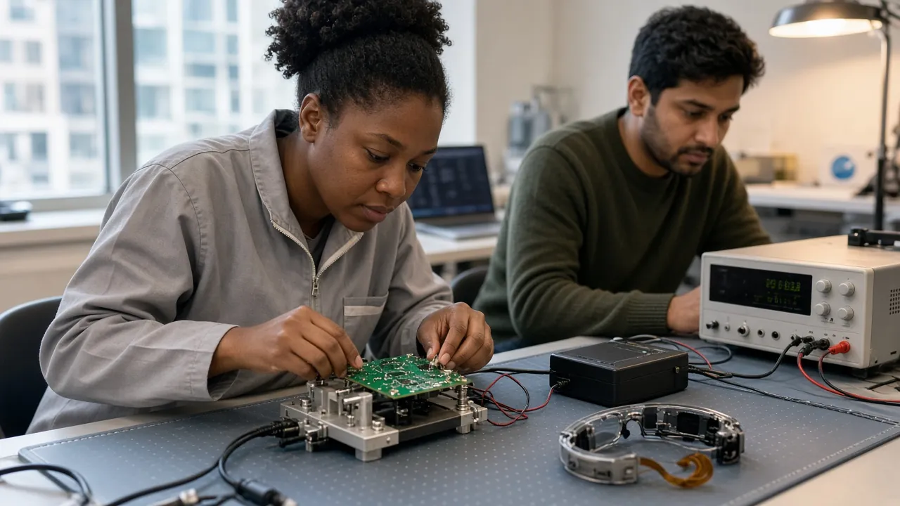
On the first assembled board from PCB assembly, follow a fixed hardware bring-up checklist:
Unpowered inspection
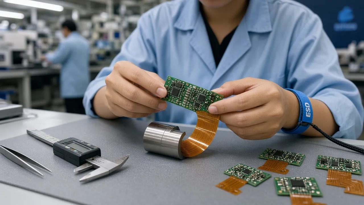
Check polarity, missing parts and shorts under magnification. Every assembled board should already have passed AOI at the factory; still re-check the first article yourself.
Current-limited power
Set the bench supply current limit just above expected idle draw. Watch for thermal hotspots as rails come up.
Rail and clock verify
Scope each rail against the power tree. Confirm oscillator amplitude and frequency before attaching a debug probe.
Attach SWD or UART
Arm SWD is a two-wire alternative to classic JTAG on Cortex-M parts. Read the chip ID, erase if needed, then load a blinky with no RTOS.
Peripheral walk
Enable one driver at a time. Log pass or fail with voltage, firmware hash and board serial.
Keep a bring-up log from day one: board serial, firmware git SHA, toolchain version, rail readings, and every anomaly. That log becomes the seed of your EVT DVT PVT testing record and feeds the validation report you will need later.
Flying probe before a dedicated ICT fixture
While layout and BOM still change, avoid a dedicated ICT bed-of-nails. Use flying-probe test plus AOI and a limited bench FCT at EVT. Decide ICT go or no-go when the board freezes toward DVT and PVT. That staging matches common NPI practice and matches how we run early builds before investing in fixtures the customer will own.
Test firmware vs shipping firmware
Production test firmware is not a cut-down shipping image. It is a separate binary with one job: prove the hardware on the line. Shipping firmware has a different job: run the product safely in the field. Mixing them is how debug menus, RF test modes and unlock keys leave the factory.
| Concern | Production test firmware | Shipping firmware |
|---|---|---|
| Purpose | Self-test, calibration write, RF and sensor limits | Product features and field updates |
| Debug access | Open for fixture programming and logs | Debug ports locked on production units |
| Radio / RF | Continuous TX/RX and channel sweeps as needed | Certified modes only |
| Keys and serials | Writes device identity and secrets once | Reads them; never re-provisions casually |
| Must ship? | Never | Yes, after golden-sample sign-off |
Build production test firmware to cover self-test of rails and buses, radio and RF checks, sensor ranges, and calibration writes into protected storage. Gate every result with numeric limits. Store firmware test results per unit by serial number so a field failure can be traced to the same station and limit set. See also our PCBA testing complete guide for how electrical and functional gates fit around the firmware path.
Programming and test on the line at DVT and PVT
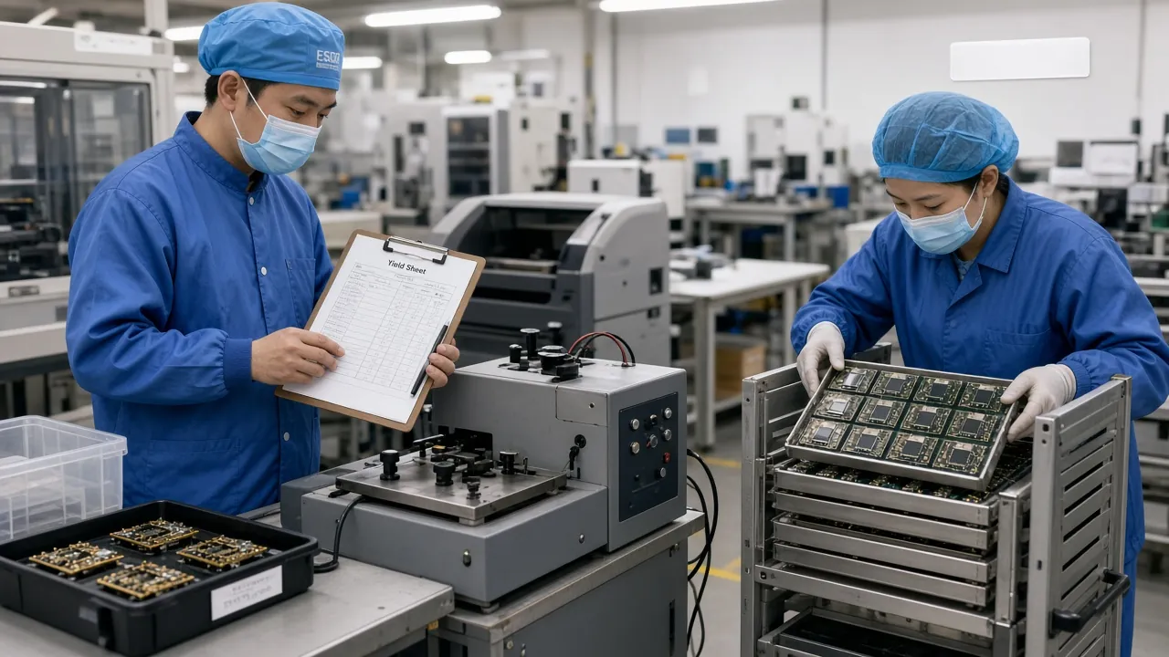
Instrumental puts DVT typically at 300 to 2,000 units with all functional test stations present and limits in place, and PVT at roughly 1,000 to 20,000 units intended for sale once they pass. At those volumes, bench SWD clips do not scale. Move to a pogo-pin programming and FCT fixture that contacts the same pads you reserved in layout.
- Pogo-pin fixture: Align to SWD/UART, power and sense pads. Customer-paid fixtures and test stations belong to the customer; keep drawings and BOM with the project package.
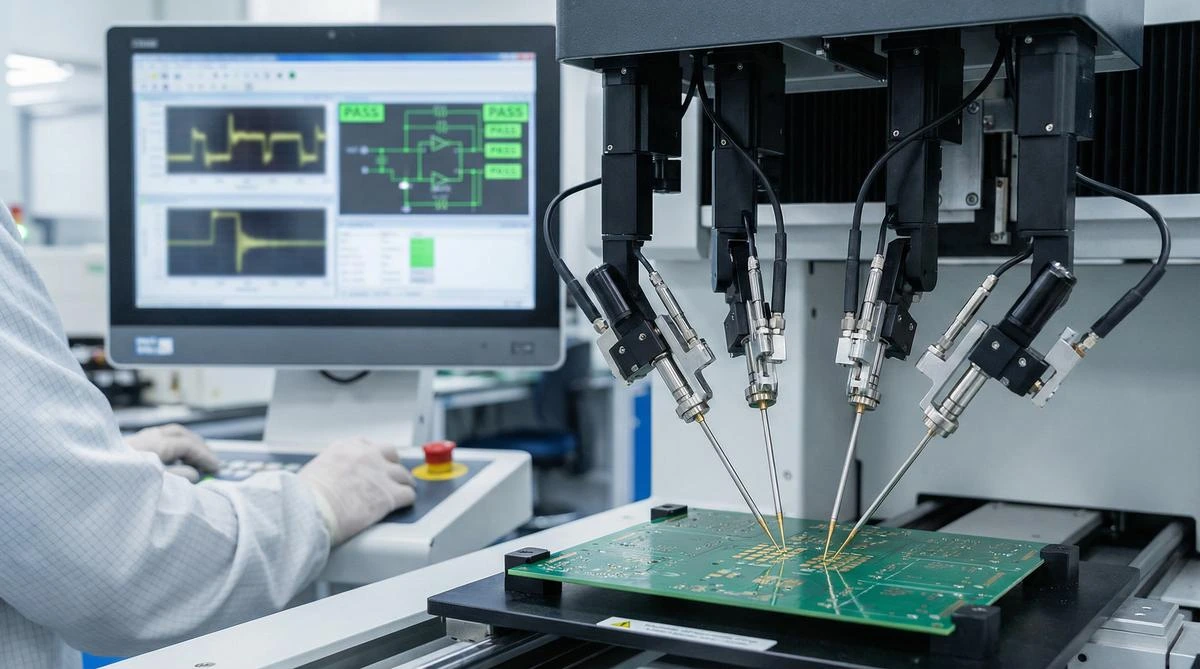
- ICT and FCT: ICT/FCT stations run production test firmware at PVT. We operate 30+ ICT/FCT test stations for that class of work. Pair with flying-probe coverage where a bed-of-nails is not yet justified.
- Serials and keys: Provision unique identity and secrets in the fixture flow. Fail closed if write-verify fails.
- Pass/fail limits: Freeze limits from DVT data before PVT rate goals. Instrumental notes that all functional test stations should already be present with limits from DVT so PVT measures true line yield.
- Results per serial: Keep every firmware test result against the unit serial for audit and RMA.
PVT ends with the test plan and fixture definitions locked. The golden sample sign-off lists the design revision, BOM, firmware release, measured values and cosmetic limits. Production batches are compared against that reference. For the broader stage gate structure, see our NPI engineering complete guide.
AOI on every board
Every assembled board gets AOI before electrical and firmware gates.
Flying probe early
Flying-probe test covers changing layouts without a fixed ICT nail map.
Production test firmware
ICT/FCT stations load the test image, not the shipping image, at PVT.
Debug ports locked
Production units ship with debug ports locked after final programming.
Results per serial
Firmware test results stay with the unit serial for life-cycle support.
Customer-owned tooling
Fixtures and stations the customer pays for remain customer property.
Shipping firmware: lock down and keep a fallback
After the last good PVT lot, flash shipping firmware and lock the debug path. Vendor guidance is consistent on this point. Nordic documents access-port protection that blocks debug until a full erase; Espressif recommends Secure Boot plus programming security eFuses that disable debug interfaces on production devices; ST production life-cycle states keep debug closed at reset unless privileged firmware unlocks it. Match the lock step to your SoC family and prove it on golden samples before volume.
Design OTA so each image is verified and the device can fall back to the last good one. Dual-slot A/B update with an explicit confirm after health checks is the common pattern on ESP-IDF and MCUboot-style systems: write the candidate slot, verify signature and hash, boot once under a watchdog, confirm only if healthy, otherwise revert. That matches how we design OTA to verify each image and fall back to the last good one on connected products. Deep product work for wearables and glasses often sits with our firmware engineering practice.
Handover that a second engineer can run
Firmware handover is incomplete if only a binary lands in a shared drive. Deliver the toolchain version, build steps and programming procedure with every release. Firmware source is delivered only when the order includes it; otherwise the customer receives binaries, and that should be stated in the SOW. Engineers attend EVT, DVT and PVT in Shenzhen so the same people who set limits can watch the line. Engineering stays in San Francisco; prototype builds, DFM and mass production run in our own factory in Shenzhen.
Pin the compiler, SDK and linker scripts. Record host OS and exact package versions so a rebuild matches the signed release.
Document clean build steps. One command path from a fresh clone to the release artifact hash.
Write the programming procedure. Probe or fixture wiring, erase options, lock sequence and verify-read.
Name who owns the source tree. Customer repo when source is ordered; otherwise Illuminious holds source and ships binaries under the contract.
Parts strategy also shapes bring-up calendars. Long-lead MCUs and RF front ends decide when the first programmable board exists; see consigned vs kitted PCBA sourcing when you plan kits for EVT. For how inspection and electrical gates surround firmware, revisit testing and inspection.
Shenzhen Founder Tour
If you want to walk a real line before you freeze fixtures, the Shenzhen Founder Tour runs Dec 6–11, 2026. Early bird is USD 3,000 until Nov 15. It is a Future Factory program. Illuminious hosts the factory stop and handles applications and payments. Apply at /startups.
Putting the checklist together
A practical hardware bring-up checklist for a connected product looks like this across stages:
- Pre-layout: Test pads, SWD/JTAG or UART, boot straps, current sense, LEDs; firmware review of the schematic.
- EVT: Current-limited first power-on, blinky, peripheral walk, bring-up log; flying probe + AOI + bench FCT.
- DVT: Production test firmware with limits; start fixture design; functional stations collecting yield data.
- PVT: ICT/FCT running production test firmware; serials and keys; results per serial; golden-sample firmware release listed.
- Ship: Shipping image only; debug ports locked; OTA verifies and falls back; handover pack complete.
That is the difference between a lab demo and a product you can support. Embedded firmware development services that stop at blinky leave yield and security risk on the table; embedded firmware development services that carry production test firmware through EVT DVT PVT testing close the loop with manufacturing. Keep the hardware bring-up checklist next to your DFM notes so the next revision does not drop SWD pads.
Ready to plan firmware bring-up with manufacturing in the room?
Talk through schematic access, test firmware scope and PVT fixture limits with the Illuminious engineering team. Engineered in San Francisco. Prototype builds, DFM and mass production in our own factory in Shenzhen.
Talk to an engineer — Instant price for configurable services · Free engineering review in 1–2 business days · Official quote within 24 hours