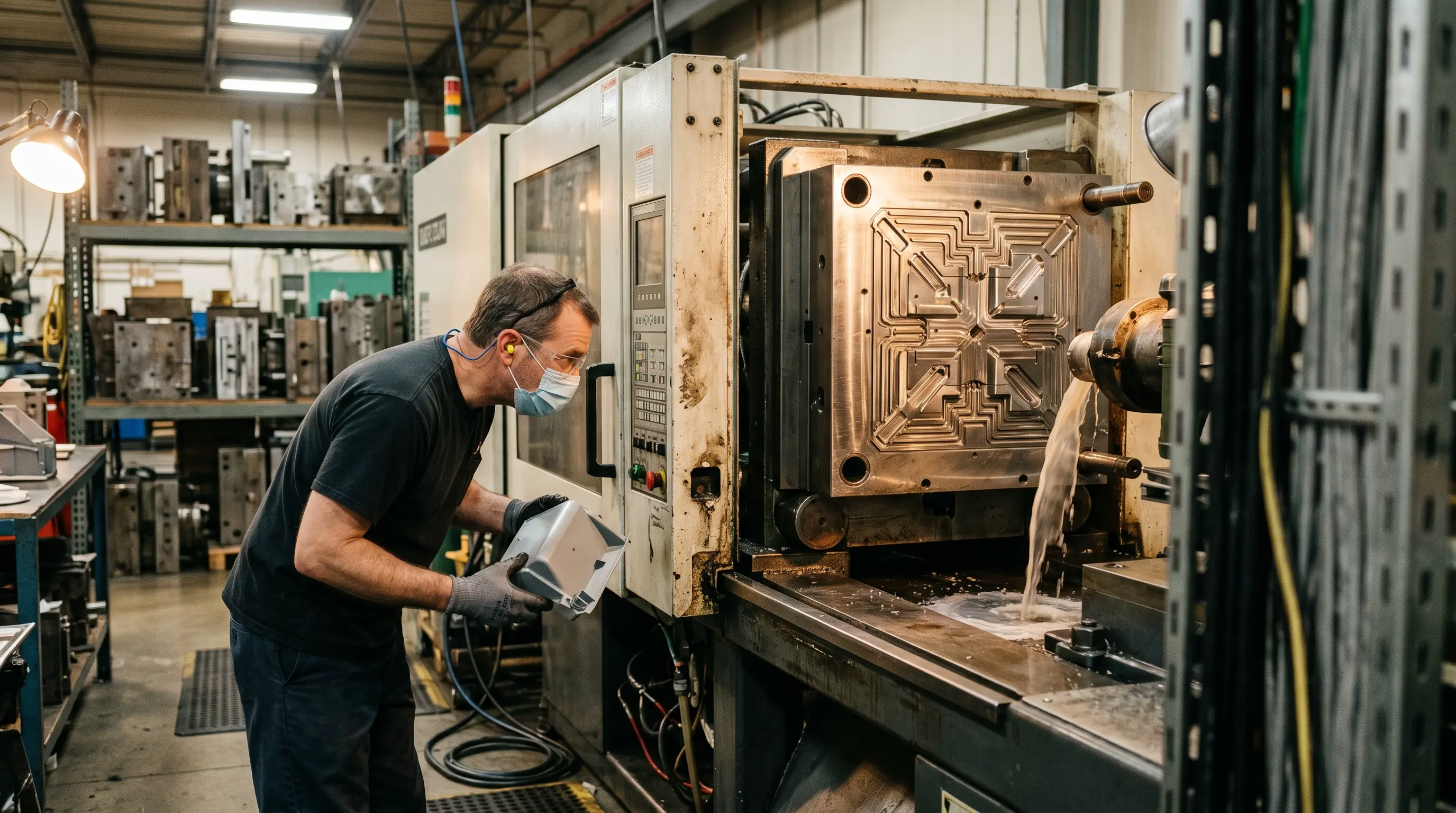
Injection molding is the backbone of high-volume plastic part manufacturing, producing millions of identical components with tolerances measured in thousandths of an inch. For hardware startups and product engineers, understanding mold design is not optional — it is the difference between a part that snaps together perfectly at unit one and unit one million, and a part that requires constant rework, secondary operations, and escalating costs. This guide walks through the entire injection mold design process: from selecting the right mold type and thermoplastic material, to applying DFM rules for wall thickness, draft, ribs, and gates, to advanced techniques like insert molding and overmolding for electronics enclosures, all the way to specifying Class 101 production tooling capable of over one million cycles.
Mold Types
Two-plate, three-plate, and hot runner molds each serve different production volumes, part geometries, and cost targets. Selecting the right mold base cuts tooling cost by 20-40%.
Material Selection
From ABS and polycarbonate to nylon, PEEK, and TPE for overmolding — your resin choice drives part performance, mold complexity, and cycle time. 85% of part failures trace back to material mismatch.
DFM Design Rules
Wall thickness uniformity, draft angles of 1-3 degrees, rib proportions of 60% nominal wall, and boss design fundamentals prevent sink marks, warpage, and ejection damage in production.
Class 101 Tooling
Production molds rated Class 101 deliver 1,000,000+ cycles with hardened steel cavities, guided ejection, and scientific decoupled molding for consistent part quality at scale.
Understanding Injection Mold Types: Two-Plate, Three-Plate, and Hot Runner
The mold base is the foundation of every injection molding project. Choosing the wrong type means either overspending on tooling or hitting production walls when volume scales. Here is how the three primary mold architectures compare.
Simplest and most cost-effective mold type. The mold splits into two halves — the cavity side (A-side) and the core side (B-side). The parting line is the only separation plane, and the runner system feeds directly into the cavity through gates on the parting line. Two-plate molds are ideal for simple geometries, low-to-medium volumes (under 500K parts), and prototyping bridge tooling. Tooling cost is typically $5,000-$25,000 depending on cavity count and complexity.
Adds a stripper plate for automatic degating. The mold separates at two parting lines: one to release the part and one to strip the runner. This allows gates to be placed anywhere on the part surface — not just the parting line — enabling better cosmetic finishes and more complex runner routing. Three-plate molds cost 15-25% more than two-plate equivalents but reduce labor for degating and improve gate placement flexibility for electronics enclosures.
Eliminates the runner entirely using heated nozzle systems. Molten plastic travels through temperature-controlled manifolds directly into each cavity, producing zero runner waste. Hot runner systems add $8,000-$30,000 to tooling cost but save 15-30% on material, reduce cycle times by 10-20%, and are essential for high-volume production above 500K units. For medical and cleanroom applications, hot runners prevent regrind contamination.
Thermoplastic Material Selection for Injection Molding
Material choice is arguably the most consequential decision in your injection molding project. It affects part strength, chemical resistance, thermal stability, mold temperature requirements, cycle time, and cost. Below is a practical breakdown of the most common injection molding resins for hardware products.
- ABS (Acrylonitrile Butadiene Styrene): The workhorse of consumer electronics enclosures. Good impact resistance, easy to mold, accepts paint and textures well. Tensile strength 40-50 MPa, melt temp 220-250°C. Cost: $1.50-$2.50/kg. Ideal for device housings, bezels, and internal brackets.
- PC (Polycarbonate): High clarity and exceptional impact resistance — 250x stronger than glass. Used for lenses, transparent windows, and high-impact enclosures. Melt temp 280-320°C, requires higher mold temperatures (80-120°C). Cost: $3.00-$5.00/kg.
- Nylon (PA6/PA66): Outstanding wear resistance, chemical resistance, and mechanical strength. Glass-filled variants reach tensile strengths of 150+ MPa. Absorbs moisture — must be dried before molding. Ideal for gears, snap fits, and structural brackets. Cost: $2.50-$4.50/kg.
- PEEK (Polyetheretherketone): High-performance engineering thermoplastic for aerospace, medical, and semiconductor applications. Continuous service temperature up to 250°C, excellent chemical resistance, inherently flame retardant. Cost: $80-$150/kg. Requires mold temperatures of 180-200°C.
- TPE (Thermoplastic Elastomer): Rubber-like flexibility for overmolding grips, seals, and soft-touch surfaces. Bonds to rigid substrates like ABS and PC during two-shot molding. Shore hardness ranges from 20A to 80A. Cost: $3.00-$8.00/kg.
Material Selection Tip
Always validate your material choice with a prototyping run of 50-100 parts before committing to production tooling. Use 3D printing for form-fit-function testing, then CNC machining for functional prototypes that simulate molded material properties. This two-stage approach catches 90% of material-related failures before you invest in steel tooling.
Critical DFM Rules for Injection Molded Parts
Design for Manufacturing (DFM) is not a review step — it is a design philosophy that must be embedded from the first CAD sketch. Violating injection molding DFM rules results in sink marks, warpage, short shots, flash, and ejection damage. Here are the rules that matter most.
Wall Thickness
Maintain uniform wall thickness throughout the part. For most thermoplastics, the ideal wall thickness is 1.5-3.0 mm. Walls thicker than 4 mm cause excessive shrinkage and sink marks; walls thinner than 0.8 mm create flow problems and filling issues. When thickness transitions are unavoidable, use gradual tapers (no abrupt steps) to manage flow and cooling.
Draft Angles
Apply 1-3 degrees of draft per side on all vertical surfaces. Polished mold surfaces can get away with 0.5 degrees; textured surfaces require 1.5-3 degrees depending on texture depth. Without draft, parts vacuum-lock in the mold, causing ejection damage, scoring, and production delays. Draft should be added to every feature — outside walls, inside walls, ribs, and bosses.
Rib Design
Ribs strengthen thin walls without adding mass, but they must follow strict proportions. Rib thickness should be 50-60% of the nominal wall thickness to prevent sink marks on the opposite surface. Rib height should not exceed 3x the wall thickness. Add 0.5-1 degree of draft to rib sides and fillet the base with a radius of 0.25-0.5 mm to reduce stress concentration.
Boss Design
Bosses provide mounting points for screws and inserts. The boss outer diameter should be 2.0-2.5x the screw diameter. Wall thickness around the boss should match the nominal wall — avoid thick bosses that cause sink. Use ribs to connect bosses to nearby walls for structural support. For self-tapping screws, design the boss core hole diameter at 70-80% of screw major diameter.
Gate Location and Type
The gate is where molten plastic enters the cavity. Gate placement affects weld line location, part appearance, filling pattern, and shrinkage. Place gates in non-visible areas when possible. Edge gates are simplest; submarine (tunnel) gates auto-degate during ejection; hot tip gates leave minimal witness marks. Avoid gating into thin sections that require long flow paths to thick sections — this causes sink and voids.
DFM Review Is Non-Negotiable
Every injection molding project should undergo a formal DFM review before tool cutting. A typical DFM review catches 15-25 design issues that would otherwise require mold modifications costing $2,000-$15,000 each. Illuminious includes DFM analysis as a standard part of every molding project, working from your 3D CAD files to identify potential problems before steel is cut.
Insert Molding vs. Overmolding: Advanced Techniques for Electronics Enclosures
Modern hardware products rarely use a single-shot molded shell. Insert molding and overmolding allow you to combine rigid plastics with metal inserts, threaded fasteners, PCBs, and soft-touch materials in a single integrated component — reducing assembly steps, improving sealing, and enhancing user experience.
Metal components or sub-assemblies are placed into the mold before the plastic shot. The molten resin flows around the insert, locking it in place mechanically and sometimes chemically. Common inserts include threaded brass nuts, stamped metal shields, threaded studs, and even populated PCBs. Insert molding eliminates secondary fastening operations, improves positional accuracy to ±0.05 mm, and creates hermetic or IP-rated seals. It is widely used for electronics enclosures, connectors, and medical device housings.
A second material is molded over a previously molded substrate. The most common application is a rigid plastic (ABS or PC) substrate overmolded with TPE for a soft-touch grip, gasket, or vibration damper. Two-shot molding (using a rotary mold) and pick-and-place molding are the two primary processes. Overmolding creates multi-material parts without adhesives, improving durability and IP sealing. Material compatibility is critical — the overmold material must chemically bond to the substrate during the molding process.
Insert Molding Benefits
Eliminates assembly steps, positional accuracy ±0.05mm, IP-rated seals, and structural reinforcement of weak points.
Overmolding Benefits
Soft-touch ergonomics, chemical bond without adhesives, multi-color aesthetics, and integrated gasket sealing.
Cycle Time Impact
Insert molding adds 5-15 seconds per cycle for manual insert loading. Robotic insert loading reduces this to 2-3 seconds.
Cost Considerations
Tooling for insert/overmold is 25-50% more expensive than single-shot molds, but eliminates downstream assembly operations.
Class 101 Mold Standards and Production Longevity
The SPI (Society of the Plastics Industry) classifies molds into five categories based on expected production life. For hardware startups planning to manufacture at scale, understanding these classifications is essential for tooling investment decisions.
- Class 101 (1,000,000+ cycles): Production-grade tooling with hardened steel cavities (HRC 48-52), guided ejection, hardened leader pins, and replaceable wear components. The gold standard for consumer electronics, automotive, and medical devices. Tooling cost: $50,000-$250,000+ depending on cavity count and complexity.
- Class 102 (500,000-1,000,000 cycles): Medium-production tooling with hardened cavities but standard-grade components. Suitable for established products with predictable demand curves.
- Class 103 (100,000-500,000 cycles): Bridge tooling for pilot production and early market entry. Often uses P20 or pre-hardened steel. Fast to build (4-8 weeks), lower cost ($15,000-$50,000), but limited lifespan.
- Class 104 & 105 (<100,000 cycles): Prototype and low-volume molds, often aluminum. Fast turnaround (1-3 weeks), minimal cost ($3,000-$15,000), but not suitable for production scaling.
When to Invest in Class 101 Tooling
Invest in Class 101 tooling when you have:
- Validated product-market fit with demonstrated demand above 100K units annually
- Frozen product design with no pending mechanical changes
- Completed NPI engineering validation including first article inspection
- Secured funding for tooling investment with ROI model showing payback within 12-18 months
Scientific Decoupled Molding Process
Scientific molding — also called decoupled molding — is a data-driven process control methodology that separates filling, packing, and holding phases of the injection cycle. Unlike traditional molding where operators adjust parameters by feel, scientific molding uses pressure curves, viscosity monitoring, and statistical process control to achieve consistent part quality across millions of cycles.
The process works in three decoupled stages:
- Filling (Stage 1): Injection speed controls the fill. The mold is filled to 95-99% using velocity-controlled injection. Fill time, pressure at transfer, and melt temperature are the critical variables.
- Packing (Stage 2): Pressure-controlled compensation for volumetric shrinkage as the plastic cools. Pack pressure is typically 50-80% of injection pressure, applied until the gate freezes.
- Holding (Stage 3): Low pressure maintained during cooling to prevent backflow and dimensional variation. The part cools uniformly until it can be ejected without distortion.
By decoupling these phases and controlling each independently, scientific molding achieves part weight consistency within ±0.1% and dimensional Cpk values above 1.67 — essential for tight-tolerance electronics housings and medical components.
Connecting Mold Design to Your Manufacturing Partner
Injection mold design does not happen in isolation. Your mold design decisions interact with every downstream process — PCBA assembly, die casting for metal components, metal stamping for EMI shields, and final product assembly. Choosing a manufacturing partner with in-house tool and die capabilities, a range of press tonnages, and integrated DFM expertise is critical for avoiding the design-to-production gaps that delay launches.
Press Range 50-1,000T
From micro-molding for precision medical components to large-format housings for industrial equipment.
Micro-Molding
Parts under 1 gram with features measured in microns — for sensors, connectors, and miniature medical devices.
Insert & Overmolding
Multi-shot and insert molding capabilities for integrated electronics enclosures with IP-rated seals.
ISO 8 Cleanroom
Controlled environment molding for medical devices, optical components, and contamination-sensitive applications.
In-House Tool & Die
On-site mold fabrication and maintenance means faster iterations, no shipping delays for mold repairs, and direct DFM feedback.
Scientific Process Control
Decoupled molding with real-time monitoring ensures part consistency from shot one to shot one million.
From Prototype to a Million Parts — Get Mold Design Right the First Time
Injection mold design is a multi-disciplinary engineering challenge that combines material science, mechanical design, thermal analysis, and process control. Getting it right means your parts are consistent, your tooling lasts, and your per-unit cost decreases as volume scales. Getting it wrong means rework, delays, and cost overruns that compound with every production run.
Whether you are designing your first prototype enclosure or specifying Class 101 production tooling for a million-unit product, partner with a team that understands the full spectrum from DFM through scientific molding. Contact Illuminious to discuss your injection molding project.