Metal stamping transforms flat sheet metal into finished precision parts at speeds up to 1,500 strokes per minute — delivering per-part costs that can be 60-80% lower than CNC machining at volume. From automotive brackets and battery contacts to medical device housings and consumer electronics shields, progressive die stamping produces billions of components annually across every manufacturing industry. But the process demands respect: a poorly designed bend radius, wrong material specification, or underestimated springback can turn a $30,000 progressive die into a scrap generator. This guide covers eight sections of metal stamping engineering — from progressive die fundamentals and material selection through DFM rules, tolerance control, deep draw design, tooling economics, and cost optimization. Whether you are designing your first custom stamped part or optimizing a million-unit production run, these principles determine whether your tooling investment delivers parts that pass inspection or parts that fail at assembly.
1,500 SPM High-Speed Stamping
Modern mechanical presses cycle at 400-1,500 strokes per minute, producing finished parts at a per-unit cost that CNC machining cannot match above 5,000-10,000 units.
±0.05mm Standard Precision
Progressive die stamping holds dimensional tolerances of plus or minus 0.05 mm on features under 50 mm, with precision stamping achieving plus or minus 0.02 mm using in-die measurement systems.
0.1mm to 6.0mm Thickness Range
From delicate electrical contacts at 0.1 mm to structural brackets at 6.0 mm, progressive die stamping covers an exceptionally broad material thickness range.
5K-10K Unit Break-Even
Stamping becomes more cost-effective than CNC machining or laser cutting at volumes above 5,000 units, with per-part costs dropping 60-80% at 100K+ volume.
Section 1: Metal Stamping Fundamentals — How Progressive Die Stamping Works
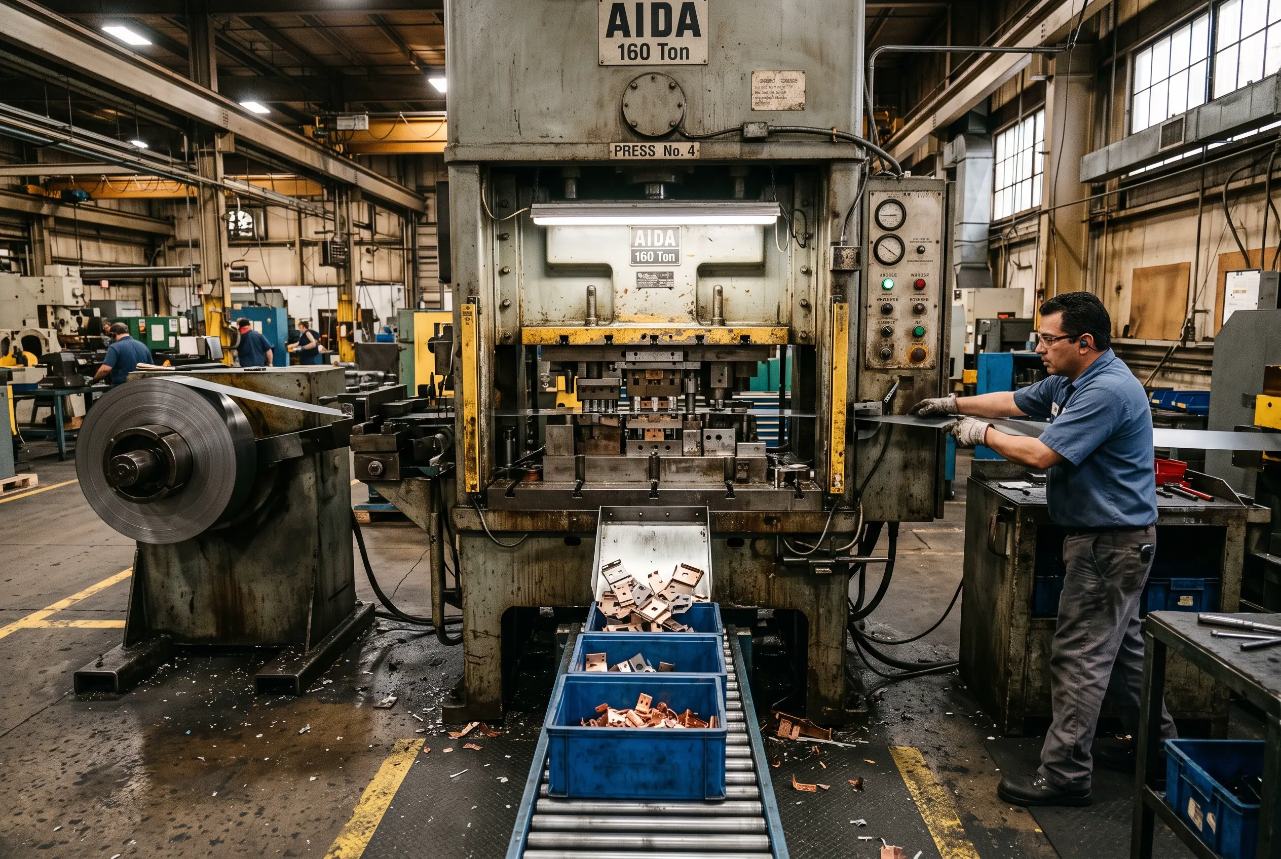
Progressive die stamping feeds a coiled metal strip through a series of die stations mounted in a single press. Each press stroke advances the strip one pitch, and each station performs one specific operation — piercing, bending, forming, coining, or blanking. The part remains attached to the carrier strip until the final station, where it is cut free as a finished component. This continuous process enables extremely high production rates with excellent feature-to-feature dimensional repeatability, because every station registers to the same strip pilot holes.
Press Types: Mechanical, Hydraulic, and Servo
- Mechanical Press: The workhorse of high-volume stamping. Flywheel-driven eccentric or crank mechanism delivers fixed-stroke cycles at 400-1,500 SPM. Ideal for blanking, piercing, and shallow forming on flat parts. Limited slide speed control makes it less suitable for deep drawing.
- Hydraulic Press: Delivers controlled force throughout the stroke, making it the preferred choice for deep drawing and heavy forming operations. Speeds of 10-60 SPM. Programmable tonnage and hold time enable complex forming that mechanical presses cannot achieve.
- Servo Press: Combines the speed of mechanical presses with the programmability of hydraulic systems. Brushless servo motors drive the slide with full motion control — programmable velocity, dwell, and position at every degree of rotation. Achieves precision forming previously possible only with hydraulic presses, at speeds approaching mechanical presses.
Progressive Die vs Transfer Die vs Compound Die
Best for high-volume, moderately complex parts. Coil-fed strip moves through 4-30 stations, each performing one operation. Highest production rate (up to 1,500 SPM), best for annual volumes above 100K units. Tooling cost: $5K-$100K depending on station count and complexity.
Best for large or deep-draw parts. Mechanical fingers or vacuum transfer move individual blanks between single-operation stations. Enables deeper draws and heavier forming than progressive dies. Lower speed (30-60 SPM) but handles parts too large or too deep for strip-fed progressive tooling.
Best for simple, high-precision flat parts. A single station performs multiple operations simultaneously — piercing and blanking in one stroke. Delivers the highest dimensional accuracy for flat parts but limited to one stroke per part. Best for low-to-medium volume gaskets, shims, and washers.
Stamping vs Alternative Processes
Choose the right process based on volume, geometry, and material requirements:
- Stamping vs CNC Machining: Stamping wins above 5K-10K units, delivering 60-80% cost reduction. CNC wins for complex 3D geometries and volumes under 1K.
- Stamping vs Die Casting: Stamping for 2D formed flat parts — brackets, shields, contacts. Die casting for complex 3D geometries with variable wall thickness.
- Stamping vs Laser Cutting: Stamping for high volume (10K+), laser cutting for prototyping and low-volume runs. Laser cutting has zero tooling cost but 10-50x slower per-part.
Section 2: Material Selection Guide
Material selection drives formability, tool wear, part performance, and per-part cost. The right material matches your application requirements — strength, conductivity, corrosion resistance — while remaining within the formability window of the stamping process.
Cold-Rolled Steel (SPCC/SPCE)
The most common stamping material. Low cost, excellent formability, suitable for plating and powder coat. SPCE (deep drawing quality) for complex forming applications. Ideal for brackets, panels, chassis components.
Stainless Steel 304/316
Corrosion resistance for food, medical, and automotive applications. 304 is most common; 316 for marine and medical environments. Work hardening during stamping increases strength but reduces formability — design accordingly.
Aluminum 5052/5086/6061
Lightweight at one-third the density of steel, with excellent corrosion resistance. 5052 is preferred for stamping due to superior formability. 6061 is heat-treatable for structural applications but harder to stamp.
Brass and Copper (C26000/C11000)
Electrical contacts, EMI shielding, and thermal management. C260 (cartridge brass) offers excellent deep draw capability. C110 (electrolytic copper) provides the best electrical conductivity for bus bars and terminals.
Specialty Stamping Materials
- Spring Steel (65Mn/SK5/SUS301): Clips, springs, and contacts requiring high yield strength and elastic limit. Heat-treated after stamping for final hardness and spring properties.
- Kovar/Invar: Electronics requiring matched coefficient of thermal expansion (CTE) for glass-to-metal seals and semiconductor packaging.
- Beryllium Copper (C17200): High-reliability electrical contacts with excellent fatigue resistance, conductivity, and non-sparking properties for hazardous environments.
- Titanium (Gr1/Gr2): Aerospace and medical implants requiring biocompatibility, exceptional strength-to-weight ratio, and corrosion resistance.
Material Thickness Guidelines
Progressive die stamping works best in the 0.3-3.0 mm range. Outside this range, consider alternatives:
- 0.1-0.3 mm: Foil and contacts — requires precision dies with tight clearances, slower press speeds
- 0.3-3.0 mm: Optimal progressive die range — maximum efficiency and tool life
- 3.0-6.0 mm: Structural brackets — requires heavier presses, thicker die plates, reduced SPM
- Above 6.0 mm: Consider CNC machining or hot forming
Section 3: DFM Rules for Metal Stamping
Design for manufacturability separates parts that stamp cleanly across a million cycles from parts that require constant die maintenance, produce excessive scrap, or fail dimensional inspection. These rules represent accumulated shop-floor experience from toolrooms producing automotive, electronics, and medical stampings.
Critical DFM Guidelines
- Bend Radius: Minimum inside radius equals 1x material thickness for soft materials like aluminum and brass. Use 1.5-2x material thickness for stainless steel and work-hardening materials. Bending across the grain requires a larger radius to prevent cracking.
- Hole Spacing: Minimum distance between holes equals 2x material thickness. Hole-to-edge distance equals 1.5x material thickness plus the bend radius. Closer spacing causes web distortion during piercing.
- Minimum Hole Diameter: Punched holes should be at least 1x material thickness in diameter. Smaller holes require drilling as a secondary operation, adding cost and processing time.
- Bend Allowance and K-Factor: Calculate the flat pattern before bending using the K-factor, typically 0.3-0.5 depending on material and bend radius. Accurate K-factor determination determines whether your formed part matches the CAD model.
- Burr Control: Stamping creates burrs on the die side of the part. Specify burr height as less than 10% of material thickness. Critical surfaces should specify burr-free or include a deburring operation in the process plan.
- Blank Layout and Nesting: Optimize material utilization through efficient strip layout. Target less than 15% scrap for high-volume parts. Nesting angle, material width, and scrap strip design all affect yield.
- Slot and Tab Width: Minimum width equals 1.5x material thickness. Alignment tabs must be designed for proper engagement without excessive insertion force.
- Coining and Embossing: Part numbers, logos, and alignment marks pressed into the surface add 5-10% to tooling cost but zero per-part cost. Design these features into the progressive die from the start.
Top 10 Metal Stamping Design Mistakes
- Specifying tight tolerances on non-functional surfaces — increases tool cost 30-50%
- Ignore grain direction on bends — causes cracking in stainless and high-strength steels
- Designing holes too close to bend lines — distorts hole geometry
- Underestimating springback — parts out of tolerance after forming
- No deburring specification — assembly issues and safety hazards
- Over-specifying flatness on as-stamped parts — requires secondary flattening
- Poor nesting layout — material waste above 25%
- Designing walls too thin for the material — tearing during forming
- No pilot hole location specified — inconsistent feature-to-feature registration
- Changing material grade after tooling is built — die clearance mismatch
Section 4: Tolerance and Precision Control
Stamping achieves remarkable precision for a bulk metalworking process, but tolerances must be specified with manufacturing reality in mind. Over-tolerancing non-functional features drives tooling cost up dramatically, while under-tolerancing critical dimensions causes assembly failures in the field.
Standard stamping: plus or minus 0.05 mm for dimensions under 50 mm, plus or minus 0.1 mm for 50-200 mm, plus or minus 0.2 mm for dimensions above 200 mm. Precision stamping with in-die measurement achieves plus or minus 0.02 mm for critical features.
0.1 mm per 100 mm for standard stamped parts. Achievable 0.05 mm per 100 mm with an additional flattening operation or stress-relief anneal. Internal stress from forming causes dimensional instability over time — critical parts may require stress relief.
Plus or minus 1 degree is standard for stamped bends. Plus or minus 0.5 degree is achievable with go/no-go gauges integrated into the die, providing real-time feedback during production.
Material springs back after bending — the die must overbend by a calculated amount. Springback varies significantly by material: aluminum 2-3 degrees, stainless steel 3-5 degrees, low-carbon steel 1-2 degrees. High-strength steels can exhibit 5-8 degrees of springback, requiring iterative die adjustment during tryout.
Section 5: Deep Draw Stamping Design
Deep drawing transforms a flat blank into a cylindrical or box-shaped cup through the action of a punch pushing material through a die ring. Unlike progressive die operations that work primarily in two dimensions, deep drawing creates significant three-dimensional geometry through controlled material flow.
Deep Draw Design Principles
- Draw Ratio (L/D): First draw up to 1.8:1 ratio of cup depth to diameter. Subsequent redraws achieve up to 0.75:1 per stage. Deep containers may require 3-5 draw operations with inter-stage annealing.
- Blank Holder Force: Prevents wrinkling during the draw — too little force causes wrinkles at the cup flange, too much force causes tearing at the punch nose. Optimal force is determined during tryout and varies by material, thickness, and draw depth.
- Materials for Deep Draw: SPCE (deep drawing steel) for general applications, aluminum 5052-O (annealed) for lightweight enclosures, stainless 304-DDQ (deep draw quality) for corrosion-resistant cups and cans.
- Applications: EV battery cans, connector housings, cosmetic enclosures, filter cups, kitchen sinks, and automotive oil pans.
EV Battery Can Deep Draw
The electric vehicle boom has made deep-drawn battery cans a critical application. Cylindrical 18650, 21700, and 4680 cell cans require multi-stage deep drawing from SPCE or stainless steel, with wall thickness controlled to plus or minus 0.03 mm for thermal management consistency. Production volumes exceed 10 million cans per month for major cell manufacturers.
Section 6: Tooling and Die Design
The progressive die is the heart of a stamping operation — a precision assembly of hardened tool steel components that must withstand millions of cycles while maintaining dimensional integrity. Die design and construction determine part quality, production rate, and per-part cost for the entire program lifecycle.
Progressive Die Components
- Die Set: The foundation — precision-ground shoe with guide pins ensuring alignment between upper and lower halves. Standard tolerance between guide pins: plus or minus 0.005 mm.
- Punch Holders and Punch Plates: Mount and locate punches for piercing and forming operations. Retainer pockets use spring-loaded ball-locks for quick punch replacement during maintenance.
- Strippers: Strip the material from punches after each stroke. Spring-loaded strippers apply controlled pressure to prevent material lift during the return stroke.
- Die Blocks: The hardened steel blocks containing the die cavities and bushings. Insert-style die blocks allow replacement of wear components without scrapping the entire die body.
- Pilots: Conical guide pins that engage pilot holes in the strip to ensure precise registration between stations — the foundation of feature-to-feature dimensional accuracy.
- In-Die Sensors: Misfeed detection, part presence, and material end-of-line sensors prevent die damage and improve first-pass yield. Modern sensors include proximity switches, fiber optics, and vision systems.
Tool Steel Selection and Die Life
Most common die material. Excellent wear resistance and compressive strength. Die life: 500K-1M parts before sharpening. Cost-effective for most stamping applications.
Specified by Japanese and Korean die standards. Equivalent properties to D2 with slightly different alloy composition. Widely used in Asian toolrooms.
Excellent toughness and red hardness. Used for punches and forming inserts subject to high impact loads. Die life: 1M-2M parts.
For ultra-high volume exceeding 1M parts. Tungsten carbide inserts in high-wear areas extend die life to 2M-5M parts. Higher upfront cost but lowest per-part tooling cost at volume.
Tooling Cost and Lead Time Benchmarks
Plan your budget and timeline against industry benchmarks:
- Simple progressive die (4-8 stations, single-plane bending): $5K-$30K, 3-6 weeks
- Complex multi-station die (15-30 stations, forming, coining, side action): $30K-$100K, 6-12 weeks
- Deep draw transfer die (4-6 stations, multi-stage draw): $20K-$80K, 6-10 weeks
- Carbide production die (ultra-high volume, 2M+ life): $50K-$200K, 10-16 weeks
- Tool maintenance: Sharpening every 50K-100K parts, 1-2 day downtime
Section 7: Secondary Operations
Most stamped parts require one or more secondary operations to meet final specifications. Designing these operations into the manufacturing flow early prevents cost overruns and quality issues during production ramp.
Deburring
Vibratory tumbling, thermal deburring, or centrifugal finishing removes sharp edges. Specify on drawing notes — adds minimal cost but prevents assembly injuries.
Tapping and Threading
In-die tapping eliminates secondary operations for high volume. Post-stamp tapping for lower volumes. Specify thread class and depth clearly.
Surface Finishing
Powder coat, plating (zinc, nickel, chrome), anodize for aluminum, electropolish for stainless. Finishing adds $0.05-$2.00 per part depending on process.
Spot Welding
Join stamped tabs to mating components. Common in battery packs, electrical assemblies, and automotive sub-assemblies.
Heat Treatment
Stress relief anneal after heavy forming to stabilize dimensions. Through-hardening for spring steel parts. Carburizing for wear surfaces.
Insert Molding Integration
Stamped metal inserts overmolded with injection molded plastic — common for threaded inserts, EMI shields, and electrical contacts embedded in plastic housings.
Section 8: Cost Optimization Strategies
Reducing stamped part cost without sacrificing quality requires optimization across material, design, tooling, and process. The most significant savings come from decisions made during the design phase — before any steel is cut for tooling.
- Material Utilization: Optimize strip layout to minimize scrap. High-volume parts should target less than 10% scrap rate. Every percentage point of scrap reduction on a million-part run saves thousands of dollars.
- Part Consolidation: Design multi-feature parts that can be stamped in one progressive die rather than assembling multiple stamped components. Eliminates assembly labor, reduces part numbers, and simplifies supply chain.
- Tolerance Optimization: Specify tight tolerances only on functional surfaces — mating features, locating holes, critical dimensions. Relax tolerances on non-critical features to reduce tool complexity and grinding operations.
- Volume-Based Tooling Strategy: Soft tooling for under 10K units uses lower-cost die materials with shorter life. Production tooling for 100K+ units uses carbide inserts for extended die life. Match tooling investment to expected volume.
- Design for Automation: Include features that enable automated feeding, orientation, and assembly — locating notches, alignment tabs, orientation holes. These features cost nothing per part but enable significant downstream labor savings.
Build Your Metal Stamping Program on Engineering Fundamentals
Metal stamping rewards teams that invest in upfront DFM, material science, and die engineering. The difference between a program that runs 2 million parts at 99.5% first-pass yield and one that struggles with 85% yield is not the press or the operator — it is the design decisions made months before the first strip feeds through the die.
Illuminious delivers progressive die stamping from 4 to 30 stations, deep draw up to multi-stage, high-speed presses up to 1,500 SPM, materials from 0.1 to 6.0 mm, in-house tool and die shop, carbide tooling for ultra-high volume, insert molding integration, IATF 16949 for automotive, and ISO 13485 for medical devices. Contact our engineering team for a DFM review of your stamping design.