Sheet metal fabrication is one of the most versatile and cost-effective manufacturing processes for hardware products, transforming flat stock into precision enclosures, brackets, chassis, and structural frames. Whether you are designing a rackmount server enclosure, a medical device housing, or an industrial control panel, the rules governing bend radii, material behavior, and feature placement determine whether your part ships on time and on budget — or spirals into rework and scrap. This guide covers everything mechanical engineers and product designers need to know: from selecting the right alloy and gauge, to calculating bend allowances and K-factors, to designing features that minimize setups and maximize nesting efficiency on a fiber laser bed.
Material Selection
Aluminum 5052-H32 and 6061-T6, stainless steel 304 and 316, cold-rolled steel — each alloy offers distinct strength, corrosion resistance, and formability trade-offs. Selecting the right grade reduces material cost by 15-30% without sacrificing performance.
Bend Design Rules
Minimum bend radii, K-factors, bend reliefs, and hole placement near bends follow strict material-dependent rules. A radius too small for the gauge causes grain cracking and scrap rates above 8% — entirely preventable with correct design.
Surface Finishes
Powder coating, anodizing, zinc plating, and chromate conversion each serve different functional and aesthetic requirements. The right finish extends product life by 5-10 years in corrosive environments.
Cost Optimization
Standardizing gauges, reducing setup count, and designing for nesting can cut fabrication costs by 20-40% without any change to part function — pure design-for-manufacturing leverage.
Material Selection for Sheet Metal Parts
Choosing the right material is the first and most impactful decision in any sheet metal design. The alloy determines formability, weldability, corrosion resistance, weight, and cost — all before a single bend is made.
Aluminum Alloys
Aluminum is the most popular sheet metal material for electronics enclosures and lightweight structural components due to its excellent strength-to-weight ratio and natural corrosion resistance.
- 5052-H32: The workhorse of sheet metal fabrication. Excellent formability with a minimum bend radius of 1× material thickness. Corrosion-resistant in marine environments. Ideal for enclosures, brackets, and panels. Typically 30-40% more expensive than cold-rolled steel but 60% lighter.
- 6061-T6: Higher tensile strength (310 MPa vs 228 MPa for 5052) but significantly less formable. Minimum bend radius of 1.5-2× thickness. Best for structural brackets and machined sheet components where strength matters more than complex bends.
- 3003-H14: Lower cost, excellent formability, good for deep draws and simple brackets. Tensile strength of 145 MPa limits use in structural applications.
Stainless Steel
Stainless steel provides superior corrosion resistance and strength, making it essential for medical devices, food processing equipment, and harsh-environment enclosures.
- 304: The most common stainless grade. Good balance of corrosion resistance, formability (min bend radius 0.8-1× thickness), and weldability. Used extensively in food-grade and medical enclosures.
- 316: Added molybdenum provides superior chloride corrosion resistance. Essential for marine and chemical processing applications. 20-30% more expensive than 304 but critical where pitting corrosion is a risk.
- 430: Lower-cost ferritic option with good corrosion resistance for indoor applications. Less formable than austenitic grades — avoid complex multi-bend geometries.
Cold-Rolled Steel (CRS)
CRS is the budget-friendly option for painted or plated enclosures where the base material will be fully covered by a surface finish. It offers excellent formability and weldability at the lowest material cost.
- SPCC/SPCD (A1008/A366): Commercial quality CRS with good formability. Minimum bend radius of 0.8× thickness. Must be finished (powder coat, zinc plate, or paint) to prevent rust.
- Galvannealed (A653): Zinc-iron alloy coating allows welding without fume issues and provides excellent paint adhesion. Standard for industrial enclosures and appliance housings.
Material Selection Quick Reference
When selecting sheet metal material, weigh these factors in order of priority for your application:
- Environment: Outdoor/marine → 316 SS or 5052 aluminum; Indoor/dry → CRS with powder coat
- Strength requirements: Structural loads → 304 SS or 6061-T6 aluminum; Non-structural → 5052 or CRS
- Weight budget: Weight-sensitive → 5052 aluminum (2.7 g/cm³ vs 7.9 g/cm³ for steel)
- Volume: High volume → CRS with powder coat (lowest total cost); Low volume → aluminum (no rust risk during handling)
- EMI shielding: Required → steel or aluminum (both provide excellent shielding when seams are properly designed)
Bend Radius Design Rules
The bend radius is the single most critical dimension in sheet metal design. Too small, and the material cracks on the outside of the bend or thins excessively on the inside. Too large, and you waste material and increase the part footprint. The correct bend radius depends on material type, thickness, and grain direction.
Minimum Bend Radii by Material
As a general rule, the minimum inside bend radius should be at least equal to the material thickness (1T). However, optimal radii vary by material:
Min bend radius: 1× thickness. One of the most formable aluminum alloys. For 1.5mm sheet, use 1.5mm minimum inside radius. Grain direction matters less than 6061 but still align bends perpendicular to grain for tightest radii.
Min bend radius: 1.5-2× thickness. The T6 temper sacrifices formability for strength. For 2mm sheet, use 3-4mm radius. Never bend 6061-T6 perpendicular to grain at minimum radius — cracking is almost guaranteed.
Min bend radius: 0.8-1× thickness. Austenitic stainless work-hardens during bending, increasing springback by 2-3° compared to aluminum. Account for this in your die selection and bend sequence.
Min bend radius: 0.8× thickness. Excellent formability. Springback is minimal (1-2°). The most forgiving material for tight bends, making it ideal for complex multi-bend enclosures.
K-Factor and Bend Allowance
The K-factor describes where the neutral axis falls within the material thickness during bending. It is essential for calculating the correct flat pattern length — get it wrong, and your finished part will be too long or too short.
- K-Factor Range: Typically 0.3 to 0.5 for most sheet metal operations. A K-factor of 0.33 is a safe default for air bending mild steel; use 0.38-0.42 for bottom bending.
- Bend Allowance Formula: BA = (π/180) × Bend Angle × (Inside Radius + K-Factor × Thickness). This gives the arc length of the neutral axis through the bend.
- Bend Deduction: BD = 2 × (Outside Setback) - Bend Allowance. Use this to calculate flat pattern dimensions directly from finished part dimensions.
- Practical Tip: Most CAD software (SolidEdge, SolidWorks, Fusion 360) includes sheet metal modules that handle K-factor calculations automatically once you specify material and thickness. Always verify with a test bend on the first article.
Bend Reliefs and Hole Placement
When a bend meets a flange edge or a feature like a hole, special design considerations prevent tearing and distortion:
- Bend Relief: When a bent flange terminates before reaching the edge of the part, add a relief notch at least 1× material thickness wide and deep. Without relief, the material tears at the bend termination.
- Hole-to-Bend Distance: Minimum 2× material thickness + bend radius from the inside bend line to the nearest edge of any hole or cutout. Holes too close to bends deform into ovals.
- Edge-to-Bend Distance: Minimum 2× material thickness from the edge of the sheet to the bend line. Short flanges are difficult to hold in press brake tooling.
- Counterbore near bends: Keep counterbores at least 3× material thickness from the bend line to avoid wall thinning and fastener interference.
For complex multi-bend sheet metal enclosures, we recommend running a DFM review before finalizing your design — catching bend relief issues at the CAD stage costs nothing, while re-cutting tooling after first article inspection costs weeks and thousands of dollars.
Surface Finishes for Sheet Metal
The surface finish serves both functional and aesthetic purposes. It protects against corrosion, provides color or texture, and creates the first impression of product quality.
Powder Coating
Electrostatic powder applied at 60-80 μm thickness, cured at 180-200°C. Available in thousands of RAL/Pantone colors and textures. Most cost-effective finish for steel and aluminum. Excellent corrosion resistance and scratch hardness.
Anodizing (Type II/III)
Aluminum only. Type II decorative anodize at 5-25 μm provides color and moderate wear resistance. Type III hard anodize at 25-100 μm offers Rockwell 60+ surface hardness for high-wear applications.
Zinc Plating
Electroplated zinc at 5-15 μm on steel parts. Provides sacrificial corrosion protection. Available in clear, yellow, and black chromate finishes. Cost-effective for high-volume steel parts that require basic rust prevention.
Chromate Conversion
Aluminum chromating (Alodine/Chem-Film) per MIL-DTL-5541. Thin protective layer that maintains electrical conductivity. Essential when the part serves as an EMI/RFI shield and needs both protection and grounding continuity.
Finish Selection Considerations
Always specify finish requirements before fabrication begins — certain operations must be sequenced around the finish:
- Hardware insertion: PEM inserts and rivet nuts should be installed before powder coating to ensure proper adhesion around the feature
- Masking: Threaded holes, grounding contact points, and mating surfaces require masking before powder coat or anodize — specify these on your drawing
- Welding before finish: All welding and grinding must be complete before finishing. Weld discoloration will show through thin coatings
- Dimensional tolerance: Powder coating adds 60-100 μm per surface. Account for this on tight-fitting assemblies and sliding interfaces
Cost Optimization Strategies
Sheet metal fabrication cost is driven by three factors: material, setup time, and processing time. Smart design decisions can reduce all three without compromising part function.
1. Standardize Material Gauges
Every unique material type and thickness combination on your BOM is a separate purchase order, a separate inventory line, and potentially a separate setup on the laser cutter. Consolidate to 2-3 standard gauges across your product.
- Recommended aluminum gauges: 1.0mm (0.040"), 1.5mm (0.060"), 2.0mm (0.080"), 3.0mm (0.120")
- Recommended steel gauges: 1.0mm (20 ga), 1.5mm (16 ga), 2.0mm (14 ga), 3.0mm (11 ga)
- Cost impact: Standard gauges are stocked in bulk by fabricators, often at 10-20% lower cost than custom-thickness sheet. Non-standard gauges may require full-coil purchase, adding weeks to lead time.
2. Reduce Setup Count
Each setup on a press brake or laser cutter is time on the machine. Reduce setups by designing parts that can be formed in a single clamping orientation where possible.
- Orient bends in sequence: Design so all bends can be completed from one orientation before flipping the part. Each flip is a setup change.
- Standardize bend radii: Use the same inside radius across all bends whenever possible. This allows the operator to use a single punch-and-die set for the entire part.
- Avoid acute angles: Bends sharper than 90° require special tooling and additional setups. Stick to 90° and obtuse angles.
- Self-locating features: Design tabs and slots that align parts for welding without fixtures. This eliminates a custom welding jig — saving $500-$3,000 per unique assembly.
3. Design for Nesting
Efficient nesting — packing parts onto a standard sheet size with minimal waste — directly reduces material cost. Design your parts with nesting in mind.
- Rectilinear profiles: Parts with straight edges and minimal curves nest more efficiently. A rectangular enclosure panel achieves 85-92% material utilization; an irregularly shaped bracket may only reach 55-65%.
- Common grain direction: If your parts require grain-direction awareness (especially 6061-T6), orient all parts on the same grain axis to avoid material waste from re-orientation.
- Tab-and-loop parts: Design mirroring parts that share a common edge on the sheet, separated by a micro-tab. The laser cuts both parts in one pass, and they snap apart after forming.
- Standard sheet sizes: Design to fit efficiently on 4×8 ft (1220×2440mm) or 5×10 ft (1525×3050mm) sheets — the standard stock sizes most fabricators keep on hand.
For hardware startups navigating the journey from prototype to production, these cost optimization strategies compound. A product designed with 3 standard gauges, uniform bend radii, and nesting-friendly geometries can cost 30-40% less to produce than an equivalent design that ignores DFM principles.
Welding and Hardware Insertion
Most sheet metal enclosures require secondary operations after forming: welding to join multiple pieces, and hardware insertion for fasteners and standoffs.
Best for steel enclosures. Fast deposition rate, strong welds on material 1.0mm and thicker. Minimal distortion on parts designed with proper weld joint access. Most cost-effective for production volumes above 50 units.
Precision welding for aluminum and stainless. Cleaner welds with minimal spatter, excellent for visible joints on finished enclosures. Slower than MIG but produces superior aesthetics. Required for food-grade and medical enclosures.
Fastest joining method for lap joints. No filler material required. Best for joining two sheets of the same material in overlapping configurations. Standard for internal brackets and panel stiffeners.
Self-clinching fasteners for sheet metal. Pressed into punched or drilled holes using a squeeze press. Available as threaded standoffs, through-hole nuts, blind rivet nuts, and flush-head studs. Must be installed after forming but before finishing for proper adhesion.
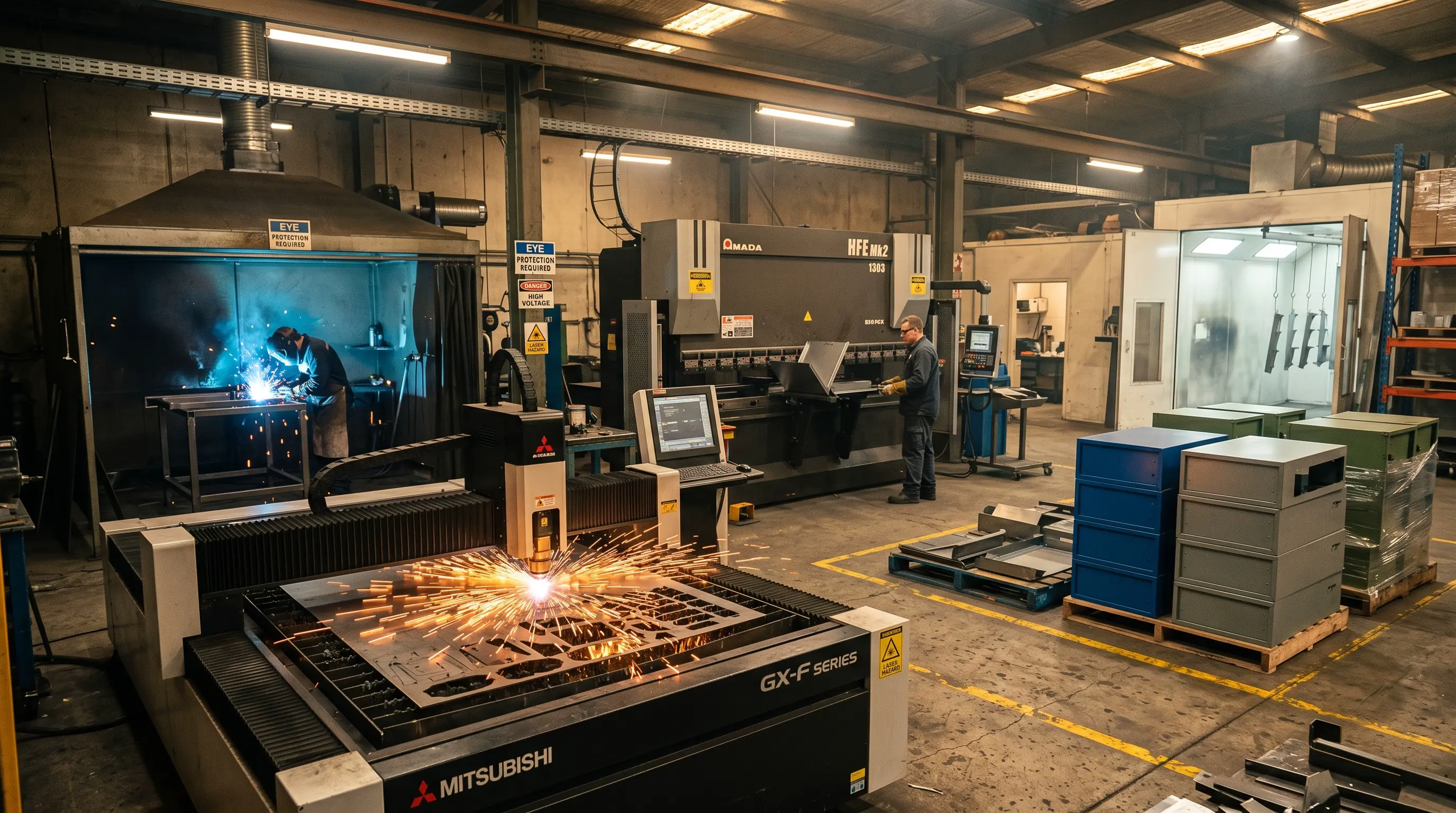
Fiber Laser Cutting
High-speed, burr-free cutting of complex flat patterns with tolerances of ±0.1mm on material up to 20mm steel
CNC Press Brake
Precision bending up to 250 tons and 4000mm bending length with ±0.1° angle accuracy
MIG/TIG/Spot Welding
Full welding capabilities for steel, aluminum, and stainless with certified welders for structural applications
Hardware Insertion
Automated PEM nut, standoff, and stud installation for assembly-ready enclosures
Surface Finishing
In-house powder coating, anodizing management, and plating coordination for complete turnkey delivery
DFM Review
Engineering review of every sheet metal design before cutting, catching issues that CAD software alone cannot predict
Whether your project requires a single custom precision-machined bracket or a full production run of 10,000 welded enclosures, the same design principles apply. For teams exploring complementary processes, metal stamping becomes cost-effective above 5,000 units for identical flat parts, while die casting offers superior complexity for thick-wall aluminum components. Early-stage prototypes can leverage 3D printing for form-and-fit validation before committing to sheet metal tooling.
Design for Manufacturability from Day One
Sheet metal fabrication rewards disciplined design. Engineers who specify standard gauges, respect minimum bend radii, consolidate setups, and design for nesting will see 20-40% lower unit costs and 30-50% faster lead times compared to designs that treat fabrication as an afterthought. The difference between a good sheet metal design and a great one is not complexity — it is intentional simplicity.
Need a DFM review on your sheet metal design? Our engineering team analyzes bend sequences, material selection, and cost optimization opportunities for every project — from prototype to production.