Rigid-flex PCB: one board that folds
No CAD yet? Our design team can take it from a sketch or a spec.
Walk Shenzhen factories with us, Dec 6–11. See the tour
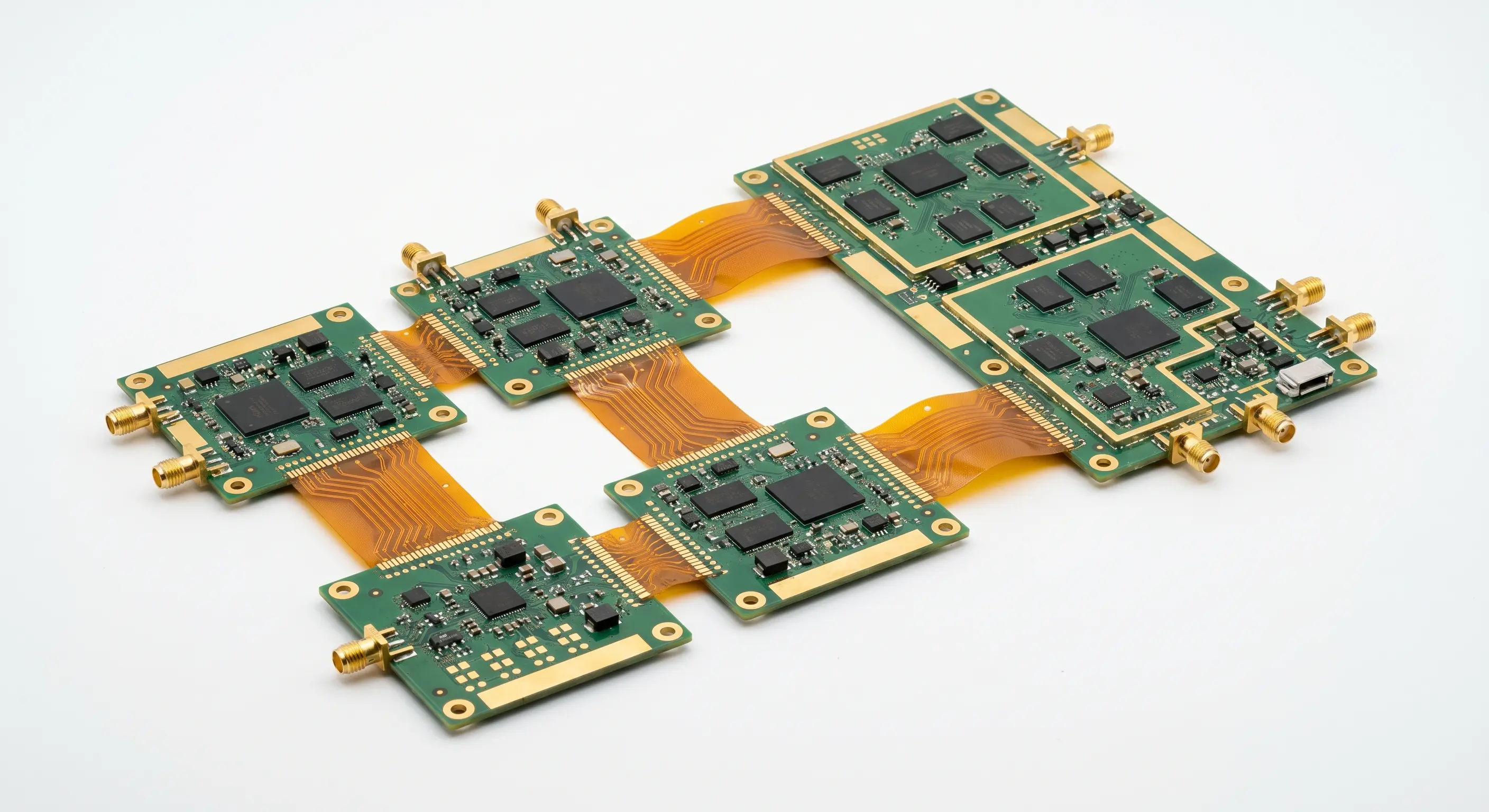
A rigid-flex board is one circuit that is rigid where it carries components and flexible where it needs to fold. The polyimide layers run continuously through the rigid sections, so there is no connector, no cable and no solder joint at the transition. Illuminious is a U.S. NPI engineering company, and our engineers check a rigid-flex board's transition zones and bends before it is built, because that is where rigid-flex boards fail. Engineered in San Francisco. Prototype builds, DFM and mass production in our own factory in Shenzhen. It replaces two boards and a cable with a single part.
In the portal, rigid-flex is a declared board class on the advanced route, and it always goes to engineering review. The construction is defined by its layer transitions, not by its layer count. It removes every board-to-board connector, and it asks for a transition zone drawn so clearly that nobody can misread it.
Where rigid-flex fits
Wearables, handheld devices, drones and anything assembled by folding are where rigid-flex earns its cost. A smart ring or a pair of smart glasses has no room for a connector. A drone camera gimbal moves in service and shakes in flight. In each case, continuous copper is lighter, smaller and more reliable than a plug and a cable.
What does rigid-flex save?
Connectors, and the failures that come with them. Each board-to-board connector is an assembly step, a set of contacts that can fret or corrode, and a part that can be mis-mated. Rigid-flex replaces them with continuous copper. In a product that vibrates, or is assembled by folding, that alone can justify the construction.
It saves volume and mass too, which is why the construction suits anything worn, held or flown. It does not save money on a simple two-board product: there, a flexible circuit with a connector at each end is cheaper and easier to rework. Boards above 30 layers, up to 40 layers, are priced by an engineer after review.
How a rigid-flex board is built
Stack-up and DFM
Our engineers plan the stack-up, the bend radius and any impedance across the transitions.
Inner layers
We process rigid and flexible layers separately, then register them for lamination.
Lamination
Rigid and flex sections are pressed together with low-flow materials that keep adhesive out of the bend.
Drilling and plating
Mechanical and laser drilling, then plating, with extra care at the transitions.
Coverlay, finish and routing
Coverlay protects the flex areas, the finish goes on the pads, and the outline is routed.
Test
Electrical test, impedance checks by TDR where the order declares impedance, and inspection before the boards ship or go to assembly.
What has to be right in the transition zone?
The place where the rigid section ends and the flexible section begins. The flexible layers must bend freely up to a defined boundary, the rigid material must stop cleanly at it, and no plated hole may cross it. Getting that geometry into the fabrication data without ambiguity matters more than any single electrical value.
A rigid-flex design is therefore reviewed as a mechanical drawing as much as a set of Gerbers. Declare the bend locations, the bend radius, whether the fold happens once at assembly or again and again in service, and where any stiffeners sit. Route copper across the bend at right angles, stagger traces on adjacent layers, and keep vias out of the flex area.
Stiffeners are a separate tool. A stiffener is a piece of FR-4, polyimide or metal bonded under a flexible area to support a connector or a part. It is cheaper than a rigid section and can be enough for a single connector on a flex tail. Declare stiffener positions and thicknesses on the drawing.
Rigid-flex capability
| Capability | What it covers |
|---|---|
| Stack-ups | 4 to 30 layers on the advanced route, mixing FR-4 rigid sections with polyimide flex layers; above 30 layers, up to 40, through engineering review. |
| Fabrication | We fabricate rigid-flex boards in the Shenzhen factory, to IPC-6013 Class 2 or Class 3 as the order states. |
| Controlled impedance | Impedance across the transitions held to ±5 %, verified by TDR testing. |
| HDI in rigid sections | Laser microvias, stacked microvias, blind and buried vias and fine-pitch BGA routing in the rigid areas. |
| Bend zones | Flex areas with balanced copper, no plated holes, and strain relief at each transition. |
| Folded assemblies | Boards that fold to fit the enclosure, assembled flat and folded once. |
| Assembly | SMT or mixed assembly in the Shenzhen factory, on carriers that hold the flex flat during printing and placement. |
| Inspection (advanced route) | Standard AOI, AOI with X-ray, or an advanced report with X-ray. |
When should I use two boards and a flex cable instead?
When the product is assembled by plugging rather than folding, when the two boards must be serviced on their own, or when volumes are too low to repay the rigid-flex process steps. A separate flexible circuit with a connector at each end is simpler to build and easier to replace in the field.
Choose rigid-flex when the connector is the failure you want to remove, when the fold happens once during assembly and never again, or when there is no room for a connector at all.
How is a rigid-flex board assembled?
Flat, on a carrier, then folded. The carrier holds the flexible sections still during paste printing, placement and reflow, so the rigid sections sit level. Parts go on the rigid sections. After test, the board is folded to its final shape, once, along the bend lines in the drawing.
Declare on the order whether the board ships flat or folded. If it ships folded, include the folded shape in the drawing and say which side faces out. Our engineers check that no part, test point or label sits where the fold puts stress on it.
Rigid-flex against a separate flexible circuit
A comparison on advanced-route options. A flex circuit of 1 or 2 layers is not an online option; it goes through engineering review.
| Consideration | Rigid-flex | Flex circuit with connectors |
|---|---|---|
| How it is ordered | Board class "Rigid-flex" on the advanced route; always goes to review | 1 or 2 layers through engineering review; 4 or more as a polyimide build, which goes to review |
| Board-to-board connectors | None; the copper is continuous | One at each end |
| Layer count online | 4 to 30, declared | 4 to 30 as a polyimide build; 1 or 2 only through review |
| Laminate family | Polyimide with rigid sections | Polyimide |
| Via technology | Through, blind and buried, laser microvia, stacked microvia | Through, blind and buried, laser microvia, stacked microvia |
| Field service | The assembly is one part | Either board can be replaced alone |
| Assembly | None, SMT, or mixed SMT and through-hole | None, SMT, or mixed SMT and through-hole |
| Free engineering review | Within 24 hours on business days | Within 24 hours on business days |
Recent work: rigid-flex for an aerospace radar
An aerospace electronics team needed multi-section rigid-flex boards with several flexible hinge zones and impedance-controlled RF traces running through them. Our engineers planned the stack-up around the hinges, and the Shenzhen factory built, assembled and inspected the boards under its AS9100 system. Read the case study
For defense programs, boards can be built to MIL-PRF-31032 on request.
Order rigid-flex online
Configure the board in Advanced PCB & PCBA. Rigid-flex always goes to a specialist, who prices it within 24 hours on business days, after the free engineering review. If the layout is not drawn yet, PCB layout designs it, and our DFM services check the bends before release. For design rules on wearables, read the flex and rigid-flex design guide. See also flex PCB.
Facts and questions
Is rigid-flex the same as a flex circuit with a stiffener?
No. A stiffener is a rigid backing bonded to a flexible circuit to support a connector or a part area; the circuit layers are still only the flexible ones. In a rigid-flex board, the rigid sections are full multilayer boards of their own, with the flexible layers running continuously through them.
How many times can a rigid-flex board be folded?
It depends on whether the fold is static or dynamic, on the bend radius, and on how the copper sits relative to the neutral axis of the bend. Declare which kind your design is, with the bend radius, and the free engineering review checks the construction against it instead of a general figure.
Can parts go on the flexible section?
Only where the section is supported and does not bend under the part, and even then it is a warning sign. Parts belong on the rigid sections; that is why the construction exists. If your design needs one on the flex, say so with the order, so the review can confirm the support and the assembly handling.
Which standards are rigid-flex boards built to?
IPC-6013, at Class 2 or Class 3 as your order states, with assemblies judged to IPC-A-610. Boards to MIL-PRF-31032 are available on request, and aerospace work runs under the Shenzhen factory's AS9100 system. Name the class and any military specification with the order, so the review scopes inspection to match.
How your official quote is prepared
A specialist prepares the official quote for every rigid-flex board from your files and stack-up, within 24 hours on business days after you submit. An engineer reviews every order before payment. The official quote it publishes is the amount you pay.
- An engineer runs a free engineering review of your files, and nothing is charged when you submit.
- You see the findings first.
- We publish the official quote with an itemized total, lead time and validity window.
- You accept the official quote, and only then does payment open.